
OWNER'S MANUALS
Digital copies of current and past Montague Owner's Manuals.
Pedal Bike Manual – Section 1:
Warnings

WARNING |
|
| As with all mechanical components, the bicycle is subjected to wear and high stresses. Different materials and components may react to wear or fatigue in different ways. If the design life of a component has been exceeded, it may suddenly fail possibly causing injuries to the rider. Any form of crack, scratches or change of colouring in highly stressed areas indicate that the life of the component has been reached and it should be replaced. Do not ride in an abusive manner. | |
CAUTION |
|
| In this manual, the CAUTION sign shows a hazardous situation which, if not avoided, could cause minor or moderate injury. | |
WARNING |
|
| In this manual, the WARNING sign shows a hazardous situation which, if not avoided, could cause death or bad injury. | |
WARNING |
|
| Great care should be taken when locking the quick release levers on the bicycle. If you do not fully understand how to operate the quick release levers, ask a bicycle dealer for assistance, or call Montague’s Customer Support Team at +1 617-491-7200. DO NOT RIDE YOUR BICYCLE WITHOUT ALL QUICK RELEASES SECURELY LOCKED. | |
Introduction
WARNING |
|
| Make sure to read this complete manual before riding your bike. Failure to do so, or failure to follow its guidelines could lead to serious injury or death. | |
Section One of this manual involves safety and bicycle care. Understanding and following this information will help you and your Montague bicycle avoid injury or damage.
Section Two of this manual covers specific operating instructions for your Montague bicycle. Even if you’re an experienced rider, you should review this section before your first ride.
Section Three of this manual gives basic instructions for making small adjustments to your bicycle and performing regular maintenance.
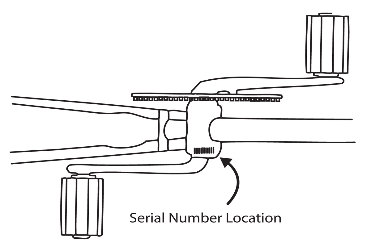
Fig. 1: The serial number is located on the underside of your bike on the bottom bracket.
- Fill in the registration form in the back of the manual that came with your bike and mail it to us at Montague Corporation, PO Box 398032, Cambridge, MA 02139
- Go to montaguebikes.com/register
The frequently updated website also gives you a link to new instructions. If you make a decision not to complete the registration, make sure you visit the website frequently. Since the components on your Montague are industry standard, repairs or replacements can be performed at virtually any retail bicycle dealer. If you have any questions about your Montague after reading this manual, or encounter any problems when folding or unfolding your bike, please visit the support section of our website at montaguebikes.com/folding-bike-support or call Montague’s Customer Support Team at 617-491-7200. A knowledgeable representative will be happy to answer any questions and help you to fully enjoy your new Montague.
Owner’s Responsibility
WARNING |
|
| Make sure to read this complete manual before riding your bike. Failure to do so, or failure to follow its guidelines could lead to serious injury or death. | |
Bicycle Type and Use Conditions
There are many types of bicycles. Each bicycle type is made for a specified use or use condition. If your use of a bicycle applies more stress than its condition limit specifies, this could cause a failure of the bicycle (or a part of the bicycle). This section shows the use condition for different types of bicycles. If you are not sure of what condition(s) apply to your bike, consult your Montague dealer or call Montague for more information.
Condition 1
These bicycles are made to ride on a paved surface where the tires are always on the ground. Condition 1 bicycles typically feature flat or drop style handlebars and 700c wheels and smooth tires. These bicycles may have accessories such as a rack, fenders, or kickstand attached.
Condition 2
Condition 2 bicycles are made to cover all the riding conditions expressed by condition 1 with the addition of gravel roads and groomed off-pavement trails. Condition 2 bicycles typically feature flat handlebars and 700c or 26” wheels. These bicycles have “semi slick” tires with light knobs on them and direct pull brakes.
Condition 3
Condition 3 bicycles are made to cover all the riding conditions expressed by conditions 1 and 2 with the addition of rough trails, small obstacles, smooth technical areas, and areas where tires are momentarily not on the ground; NOT FOR JUMPS. These bicycles are typically referred to as Mountain Bicycles or Cross Country Mountain Bicycles. Condition 3 bicycles typically feature flat handlebars and 26” or 27.5” wheels. These bicycles have wider tires with large knobs on them and direct pull or disc brakes.
WARNING |
|
| If your use of a bicycle applies more stress than the specified use condition of the bicycle, the bicycle or its parts can be broken or damaged. Riding a bicycle that is damaged could decrease your control and cause you to fall. Do not ride in use conditions that apply more stress than the limits of the bicycle. If you are not sure of the limits of the bicycle, consult your dealer. | |
Parts of Your Folding Bike
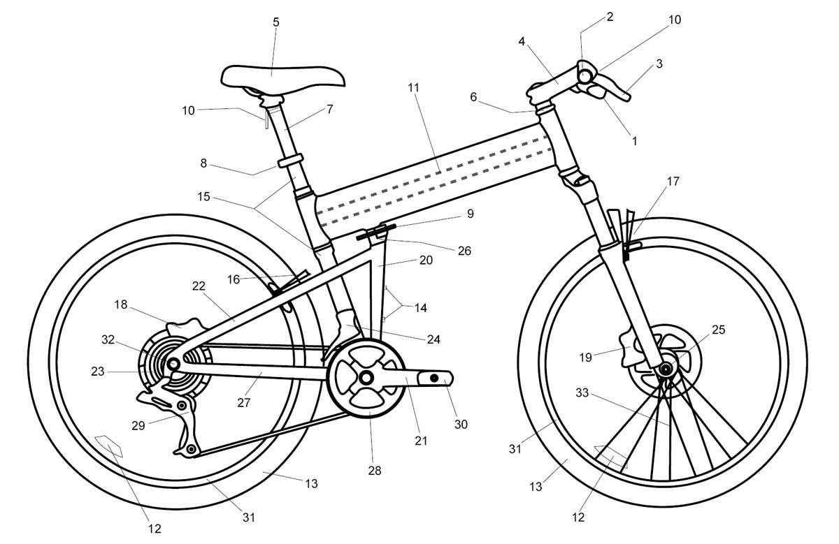
1. shift levers
2. handlebar
3. brake lever
4. stem
5. saddle
6. head set
7. seat post
8. seat post quick release
9. DirectConnect™ frame quick release
10. reflectors (front & rear)
11. boom tube (also comes with 2 tubes)
12. spoke reflectors (front & rear)
13. tire (front & rear)
14. water bottle mounts
15. seat tube
16. rear V-brake or
caliper brake (select models)
17. front V-brake or
caliper brake (select models)
18. rear disc brake
(select models)
19. front disc brake
(select models)
20. down tube
21. crank arm
22. seat stay
23. cassette
24. front derailleur
25. CLIX® front wheel quick release
26. frame Direct Connect™
27. chainstay
28. chain wheel
29. rear derailleur
30. pedal
31. rim (front & rear)
32. rear wheel quick release or nut
33. wheel spokes
Before Your First Ride
WARNING |
|
| A bicycle that does not work properly can cause you to lose control and fall. Inspect the entire bicycle thoroughly before every ride, and do not ride it until any problem has been corrected | |
Make Sure your Bicycle is the Correct Size
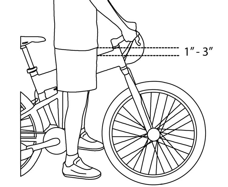
Fig. 3: Bicycle stand over
You should ask your dealer or Montague to help find a bicycle that has the correct dimensions for your body. You should be at least 1” of clearance above the boom tube (2-3” clearance for mountain bikes)when you stand over the bicycle (Fig. 3). You can adjust the saddle and handlebar (on select models) to offer the best comfort and performance. Before you make these adjustments, refer to the Proper Maintenance and Adjustments section. Montague bicycles are designed for a maximum total weight of rider plus luggage of 250lbs or a maximum total weight of rider plus luggage plus bicycle of 280lbs.
Know How your Bicycle Operates
The elements of your bicycle, if not used correctly, can decrease your control of the bicycle. Before you ride fast or outside a controlled environment, learn the operation and performance of all the mechanisms of your bicycle. Practice using the various features of your bicycle at slower speeds in a flat, open area before taking the bike on public roads. If your bicycle does not operate as necessary, or if different parts are necessary for the safe operation of your bicycle, speak to your dealer or call Montague Corporation +1 617-491-7200.
Check your Brakes, Steering, and Quick Releases
Press each hand lever to ensure the brakes are moving freely and stop the bike. Braking performance changes with riding conditions. Practice braking at low speeds before taking your bike out into high traffic areas or trails. If your brakes are not working properly, DO NOT ride your bicycle. Take the bike to your local dealer for service.
Check that all quick releases (front wheel, frame, seatpost, and on some models rear wheel, caliper brake and Octagon) are fastened. Nothing should rattle or be loose.
Review Riding Safely on and Riding Instructions before attempting to ride your Montague bicycle. Check the steering as shown in Fig. 7.
Prevent Toe Overlap
Some frame sizes, especially smaller sizes, use a short-wheelbase design with the front wheel close to the pedals. Increasing the distance between the front wheel and the pedals could place the handlebar too far away or make the steering unwieldy. On bicycles where this distance is short, when the handlebar is turned during very slow speeds your foot or toe-clip could overlap or touch the front wheel or fender (Fig. 4).
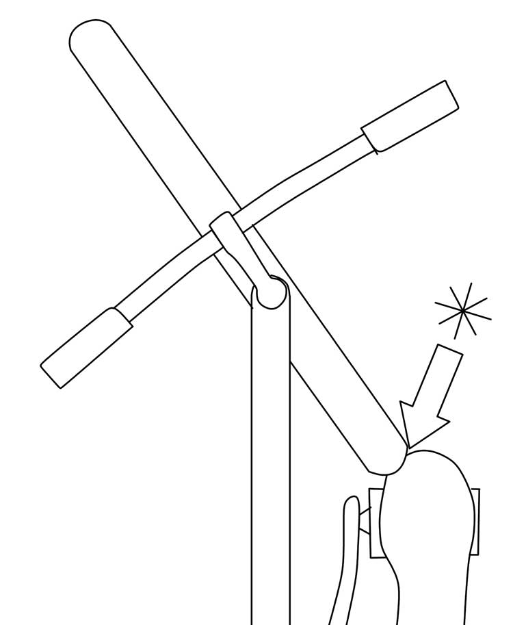
Fig. 4. Toe overlap
This overlap is affected by the size of your feet, the length of the crankarms, and the pedals you choose. At usual speeds, the handlebar does not turn suffiently for overlap to occur. When you ride slowly, do not pedal when the handelbar is turned.
WARNING |
|
| If your foot or toe-clip touches the front wheel or fender, this could decrease your control and cause a fall. Do not pedal when you turn at slow speed. | |
Hot Spots, Moving Parts, Sharp Areas, and Pinch Points
Some parts of your bicycle can injure you if mishandled. Sharp areas include chainring teeth, pedals, and brake discs. Brakes and their parts get hot. Moving parts can cut skin and even break boes. Clamps and pivoting parts such as brake levers can pikch, as can the chain where it runs over sprocket teeth.
Frame or Fork Problem
Frame problems are uncommon, but an early warning sign can be the presence of a shake or shimmy while riding at some speeds. If you experience this, or any other problem, decrease speed immediately and do not ride the bicycle. If your bicycle behaves in an unusual manner or makes excessive noise, take the bicycle to your dealer for service.
WARNING |
|
| A frame or fork problem can decrease control and cause a fall. If your bicycle gets a shimmy or any other issue, decrease speed immediately and take it to your dealer for service. | |
Lifespan of a Bicycle
Bikes and the components that comprise them are not indestructible. Depending on the riding forces, conditions, and mileage endured, you should replace your bike or its parts at an appropriate frequency.
The safe life of a part is determined by its construction, materials, and wide range of operating conditions, so it is not possible to provide a precise schedule for replacement. Any cracks, scratches, or significant color changes indicate that a component’s life has been reached and should be replaced. Consult your dealer if you have any areas of concern.
Good maintenance practices and frequent inspections will ensure that you get the most out of your investment.
WARNING |
|
| Bikes are subjected to wear and high stresses. Different components react to these stresses differently. If the design life of a component is exceeded, it may suddenly fail and cause injury to the rider. | |
Before Every Ride
WARNING |
|
| This is not a comprehensive maintenance program. Montague recommends that you have your bicycle tuned and safety checked by a bicycle technician on a regular basis but no less than annually. If you notice any irregularities in your bike and/or its performance take it to a bicycle dealer before attempting to ride. Overuse of any brake system may cause loss of control resulting in personal injury. | |
Ensure that your bicycle is in proper working condition each and every time you ride. If a part of the bicycle does not function correctly, consult this manual and bring the bicycle to your local dealer for repair.
WARNING |
|
| A bicycle that does not work properly can cause you to lose control and fall. Do not ride a bicycle with a part that is damaged; replace the part before riding. | |
Before Each Ride Checklist
- Frame and Fork
- Wheels
- Tire Inflation
- Brakes
- Handlebar and Stem
- Saddle and Seatpost
- Lights and Reflectors
- Suspension
- Quick Releases
- General
Carbon Fiber Components
Some models have carbon fiber components. Pound for pound, carbon fiber is stronger than steel or aluminum. But it behaves differently when it is overloaded in an accident or impact. An overloaded metal part will bend or deform before it breaks, showing evidence of the load (Fig. 5). An overloaded carbon fiber part will not bend or deform, so a damaged carbon part (with reduced strength due to the damage) may look normal – even after the same load that bent the metal part. But when the sum of the forces finally exceeds the strength limit of the carbon fiber, the carbon fiber part breaks, it does not bend (Fig. 5).
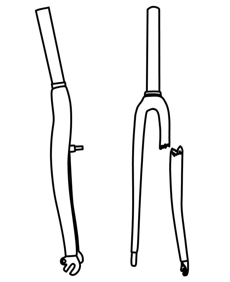
Fig. 5. Overloaded forks. The metal fork on the left bent when overloaded. The carbon fiber fork on the right failed at a much higher load, but separated.
In an accident or impact that does not break the carbon fiber, the carbon fiber could have internal or hidden damage but appear normal. If that occurs, please carefully read these instructions and examine the carbon fiber. These tests are not conclusive: If you are not sure a part is safe, replace it.
WARNING |
|
| A carbon fiber part that has damage can break suddenly, causing serious injury or death. Carbon fiber can conceal damage from an impact or crash. If you suspect your bicycle has had an impact or crash, immediately stop riding the bicycle. Replace the part before riding, or take to your dealer for service. |
|
Carbon Fiber Test
To examine for surface problems
1. Clean the part fully with a moist cloth.
2. Look carefully for problems. These include scratches, gouges, cracks, discoloration, loose fibers, or other surface imperfections.
To examine for a change of the rigidity (flex test):
Do not ride, but use the part in the usual manner while someone carefully examines the part for movement or unusual noise.
To examine for delamination (tap test):
1. Clean the part fully with a moist cloth
2. With a coin, tap near the possible damage.
3. Listen carefully for variations in sound. Tap on the part where it is in good condition (or use a part that is almost the same). Compare the sound. Anything unusual, especially a hollow sound, indicates a problem.
Protect from Extreme Temperatures
Protect carbon composite components from extreme temperatures when storing or transporting your bike.
Allow carbon composite components to cool off or warm up before you ride. Do not store a bike with carbon components in places where the temperature will exceed 66.5°C (150°F). For example, do not leave your bike lying flat in a black pickup truck bed in the desert sun or under the glass of a hatchback auto.
Excessive heat, such as that used in powder coating, or any open flame, may damage the adhesive which joins carbon composite parts. Do not exceed 180°F (82°C) exposure to your frame.
Examine the Frame and Fork
Before and after each ride, examine your bicycle for signs of fatigue and stress. Such signs may manifest themselves in the form of:
- Dents
- Cracks
- Scratches
- Deformation
- Discoloration
- Unusual Noises
If your bicycle receives a high force load or impact, fully examine all the parts of your bicycle. High force loads include crashes and strong impacts that do not cause you to crash. If you are unsure whether or not you should replace a part, speak to your local dealer.
Examine the Wheels
Check the attachment of both wheels. With the quick release lever in the “close” position, pick the front wheel off the ground and apply force to the wheel in a downward motion (Fig.30 page 29). The wheel should remain securely in place. Grab your wheel and try to move it from side to side. Check the rims for cracks, discoloration, and trueness. If there is any movement or irregularity in the wheel do not ride your bike. Take it to your local dealer for service.
When the quick release lever is properly adjusted and in closed position you should not be able to rotate the lever in a circular motion (parallel to wheel). This is different from the “flipping” motion, used to open and close the quick release lever (Fig. 57 page 44). Repeat the same steps to check the rear wheel.
WARNING |
|
| A wheel quick release that is not properly adjusted or closed can cause the wheel to loosen or come off, suddenly stop its rotation, or decrease your control, causing you to fall. Make sure the wheels are correctly attached before riding your bicycle. | |
Note that different systems attach bicycle wheels to the frame: threaded axle nuts, and multiple styles of a lever actuated quick-release system. Make sure the wheels are straight. Turn each wheel and look at the rim when it goes through the brake pads or the frame. If the rim wobbles up and down or from side to side, repair the wheel.
Examine Tire Inflation
WARNING |
|
| Excess air pressure can cause the tire to explode off the rim, causing hearing loss or, if riding, a loss of control. Use a hand pump with a reliable pressure gauge and do not overinflate. | |
Inflate the tires to the air pressure recommended on the sidewall of the tire. Improper tire pressure will cause excessive wear, causing premature replacement. Pressurized, unregulated pumps should not be used for this task.
The tire should be properly seated in the rim and the fitting of the tire bead and rim bead should be checked. If the tube is pinched between the tire and the rim, it can explode when inflated. Ensure that the tire is not cracked or unevenly worn. Check for bulges. Check that the valve is straight in the rim. Irregular tires should be replaced immediately.
Examine the Brakes
WARNING |
|
| A brake system that has damage or is not adjusted properly could decrease your control and cause you to fall. Inspect brakes fully before each ride, and do not ride if brakes are not operating correctly. Make adjustments as needed or take to your local dealer for service. | |
Follow the inspection instructions for the type of brake equipped on your bicycle:
• Hand-rim brake: a cable connects a hand lever to the brake. The lever causes brake pads to apply pressure to the rim. Pull the lever to make sure the brake moves freely and stops the bicycle. If the lever can be pulled to the handlebar, the brake is too loose. When brakes are not applied, brake pads should be 1 to 2mm from rim. If brake pads are too near the rim, brake is too tight. The brake pads should be in line with the rim surface (Fig. 6)
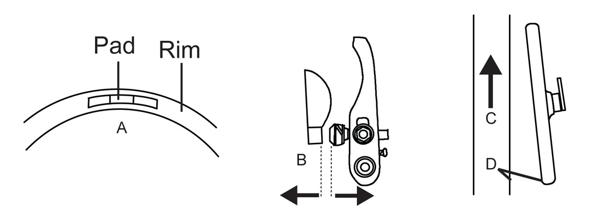
Fig. 6: Pad alignment. A: Brake pad lined up with rim surface. B: Brake pad and rim should be parallel. C: Rim direction. D: Toe-in of .5-1.0mm.
Disc brake: a cable or hydraulic hose connects a hand lever to the brake. The lever causes the brake to apply pressure to a disc attached to the hub.
CAUTION |
|
| Disc brakes and discs get very hot during use and could burn skin. Also, the disc edges can be sharp and could cut skin. Do not touch the disc or disc brake when it turns or when hot. | |
Pull the brake lever to make sure the brake moves freely and stops the bicycle. If the brake lever can be pulled to the handlebar, the brake is too loose. When brakes are not applied, the brake pads should be .25-.75mm away from the disc. If the pads are too near to the disc, the brake is not in line or it is too tight and the brake should be adjusted.
Examine the Steering
WARNING |
|
| Never ride a bike with an improperly adjusted handlebar or stem as this can cause you to lose control of the bike, leading to serious injury or death. Also, handlebar ends that are not plugged or covered can cut in a crash. | |
Make sure the stem is in line with the front wheel and correctly attached to the fork and handlebar.
To examine the connection to the fork, try to turn the handlebar from side to side while you hold the front wheel between your knees (Fig. 7).
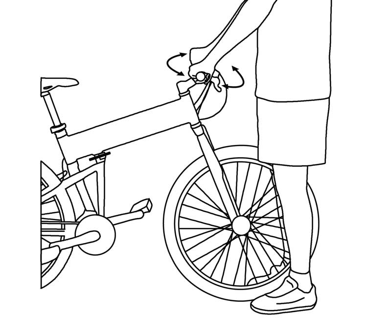
Fig. 7: Try to turn the handlebars while holding the front wheel between your knees.
To examine the connection of the handlebar, try to twist it in the stem. The handlebar should not move or be loose. Make sure that no cables are pulled or caught on the bicycle when you turn the handlebar. If the handlebar or stem is loose to turn, bring the bike to a local dealer for inspection.
Saddle and Seatpost
Make sure the saddle is correctly attached and the minimum insertion line on the seatpost is not showing. Try to turn the saddle and seatpost in the frame, and try to move the front of the saddle up and down. The saddle should not move or be loose. If the saddle is loose try adjusting it using the instructions on pages 21 & 38.
Suspension
On select models, adjust your suspension for your use, and make sure that no suspension component can “bottom-out”, or be fully compressed while riding.
Quick Releases
Check that all quick releases (front wheel, frame, seatpost, and on some models rear wheel,caliper brake, Octagon® stem, and RackStand latch) are fastened. Nothing should rattle or be loose.
Lights & Reflectors
Make sure lights operate correctly and that batteries are charged. Make sure all reflectors are clean and in their correct position.
To install a light bulb
WARNING |
|
| Without correct lights and reflectors, it will not be easy for you to see or for other people to see you. If you cannot see, or other people cannot see you, you could have an accident. Use a front light, a rear light, and reflectors when you ride in low visibility conditions. | |
The bulb has markings that indicate the
correct voltage. When purchasing spares or replacements, take the bulb with you to the store to make sure you purchase the correct bulb for your light.
1. Find the lens set-screw on the rear of the light.
2. Turn the screw counterclockwise. Remove it.
3. Turn the lens one quarter-turn clockwise. Pull the lens assembly off of the bulb-attachment.
4. Turn the bulb counterclockwise. Remove it. • Be careful not to crush the glass of the bulb. Do not dislodge the wire in the base of the bulb-attachment.
5. Turn a new bulb in until it is slightly tight.
6. Put the lens on the bulb-attachment.
Turn the lens one quarter-turn counterclockwise.
7. Put the lens set-screw in the rear of the light. Tighten the screw.
General
Check to make sure nothing seems loose or rattles. Check that both pedals are properly threaded into the crank arms.
Riding Safely
Different localities and countries have different laws governing bicycle riding on public roads, and you should check with local officials to make sure you are complying with these laws.
• For your safety, always wear a helmet that meets CPSE or CE safety standards. In the event of an accident a helmet can protect you from serious injury and even death. A bicycle dealer will be happy to assist you in the selection of a helmet and other useful accessories.
• Obey all local traffic laws. Obey red and green lights, one-way streets, stop signs, etc.
• Ride with the traffic, not against it. Ride single file in a straight line.
• Have a satisfactory signaling device (bell, horn, etc.), to warn of approach. Ride Defensively (expect the unexpected).
• Give pedestrians the right of way. Do not ride too close to pedestrians and alert them if you intend to pass from behind.
• Slow down at all street intersections and look to the left and right before crossing.
WARNING |
|
| Proper use of your front brake is vital to ensure safe, efficient stopping. To avoid misuse and potential injury, do not apply sudden or excessive force to your front brake. Doing so may cause your rear wheel to lift off the ground and/or your front wheel to slip from under you. Apply both brakes at the same time and shift your weight backward on the bicycle while braking. | |
Always use proper hand signals for turning and stopping. Give signals 100 ft. before stopping or turning and always return both hands to the handlebars before stopping or turning.
• Watch for cars pulling out into traffic and for the sudden opening of car doors.
• Avoid potholes, drainage grates or other road surface hazards. Cross railroad tracks at a right angle. Be careful when riding on soft road edges, gravel, sand and uneven surfaces. Ride slowly and avoid quick turns when riding on these surfaces.
• Never hitch on to other vehicles, do not “stunt” ride or race in traffic. Do not weave in and out of the traffic or swerve from side to side.
• We do not recommend fitting a child-seat to any Montague bicycle. However, if one is fitted, care should be taken to fit suitable coverings to prevent trapping of children’s fingers.
A crash can put extraordinary stress on bicycle components, causing them to fatigue prematurely. Components suffering from stress fatigue can fail suddenly, causing loss of control, or serious injury. For more information and a guide for safe on-road and off-road riding, see www.montaguebikes.com/support.
Caution: Wet Weather Riding
Brakes do not work as well under wet conditions as they do when dry. In wet weather, special precautions must be taken to ensure safety in stopping. Proper adjustment and cable lubrication will help, but the major precaution rests with you, the rider. Increased brake pressure is needed in wet or rainy weather and care must be taken to maintain safety in these conditions.
WARNING |
|
| Wet or inclement weather can make a bicycle difficult to control. Decrease your speed and use extra caution, or use other types of transportation. | |
Ride slower than normal and apply your brakes sooner than regular conditions would require.
When wet surfaces freeze, traction is further decreased. Brake power could decrease. Adjust your speed.
Be Seen (Especially at Night)
Your bicycle has a full set of reflectors. Make sure the reflectors are clean and in the correct position. As useful as these reflectors are, they do not help your vision. They do not make you easy to see unless light is pointed at them. You should see and be seen. If you ride at dusk, at night, or in low-visibility conditions, speak to your dealer to find equipment or materials to help your vision and make you easier to see.
WARNING |
|
| When you ride in low-visibility conditions such as fog, dusk, or night, you might be difficult to see, which could lead to a collision. Your bicycle is equipped with reflectors. In addition to keeping your reflectors clean, and properly affixed to your bicycle, use a front light and rear light when you ride in conditions with low light or low visibility. Wear bright, reflective clothing when riding in poor lighting conditions. Consult your local bike shop to find accessories and clothing appropriate for your riding needs. | |
Think Safety
Think about safety when you ride. You can prevent many bicycle accidents if you think about safety. For example:
• Check your bike before every ride, making sure that your brakes are operating effectively and everything is in perfect working condition.
• Do not ride ‘no hands.’
• Do not ‘ride double.’
• Avoid riding in large groups, as this can force you to ride too close to other riders, making it difficult to see other vehicles and road hazards. When another rider is close, a sudden change in direction or speed can cause you to lose control.
• Do not ride above your skill level.
• Do not ride too fast – with increased speed comes increased risk. Higher speed causes small bumps to create large impact forces on your forks and frame, and results in higher forces and risk of injury if a crash occurs.
• Do not ride with loose objects attached to the handlebar or other parts of the bicycle, for example with a pet or its leash.
• Never carry other riders or packages, as they may obstruct vision or proper control of the bicycle.
• Do not ride while intoxicated or while taking medications which can make you drowsy.
• Ride carefully when off-road, staying on trails, and not riding over rocks, branches, or depressions.
• When approachng a descent, decrease speed, move your weight to the rear, and use the rear brake more than the front.
• Do not ride abusively, ride within the Use Conditions specified for your bicycle type
WARNING |
|
| You add to your risk of injury when you use your bicycle incorrectly, for example when you: • Jump your bicycle • Ride over sticks, debris, or other obstacles • Do bicycle stunts • Ride in severe, off-road terrain • Ride fast, in competition, or “downhill” • Ride in an unusual mannerSuch examples add to the stress on each part of your bicycle. High stress can cause the frame or a part to break and increase your risk of injury. To decrease your risk of injury, use your bicycle correctly. |
|
Riding Instructions
Using your Brakes
Always ride with a safe distance between you and other vehicles or objects. Use your brakes. Adjust speed, braking distances, and braking force based on the conditions you ride in.
WARNING |
|
| Fig. 8. Do not over-use the front-wheel brake; the rear wheel can lift and cause you to lose control. | |
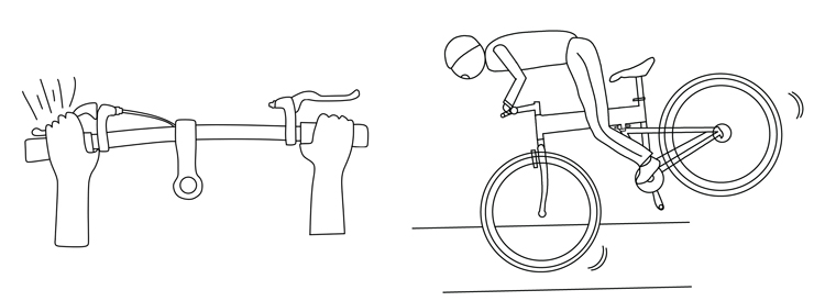
Fig. 8. Do not over-use the front-wheel brake; the rear wheel can lift and cause you to lose control.
Apply pressure to both brakes at the same time. Overuse or incorrect use of a front brake could cause the rear wheel to lift from the ground which can cause an accident (Fig. 8).
Many models of modern brakes are very powerful; they are made to stop a bicycle in wet or muddy conditions. If you think your brakes are too powerful, transport your bicycle to your dealer for adjustment or replacement of the brake system.
Note: In most countries around the world, including the U.S.A., France, and Germany, the left brake lever operates the front brake, and the right brake lever operates the rear brake (note: bicycles manufactured for the United Kingdom and some other countries switch these and the left brake lever operates the rear brake and the right brake lever operates the front brake).
Changing Gears Correctly
The multi-gear system provides a means of maintaining a constant pedaling rate, regardless of road level conditions.
The gears are activated by cables connecting the shift levers located on the handlebar to the derailleurs.
If your bicycle is equipped with twist shifters, rotating the twist shifters towards you moves the chain from one chainring (or sprocket) to the next larger chainring (or sprocket). Rotating the twist shifters away from you moves the chain from one chainring (or sprocket) to the next smaller chainring (or sprocket).
If your bicycle is equipped with shift levers, pushing the thumb shift lever away from you moves the chain from one chainring (or sprocket) to the next larger chainring. Pulling the index finger shift lever towards you moves the chain to the next smaller chainring (or sprocket).
The left shifter controls the front derailleur and the right shifter lever controls the rear derailleur. To shift, continue pedaling at a steady pace while operating the shifters and engage the gear you find most comfortable.
For easiest pedaling (while going uphill), position the chain over the smallest chainring in front and the largest sprocket in back. For hardest pedaling (while going downhill or quickly), position the chain over the largest chainring in front and the smallest sprocket in back.
For models with an external derailleur, pedals and wheels must be turning forward while shifting gears. Never pedal backward while shifting gears and never force the twist shifters or shift levers.
To change gears on models with internal gear hubs, move the pedals to the rear or do not move them. If you must change gears while you pedal, decrease your pressure on the pedals. Too much tension on the chain prevents the correct operation of the gear change mechanism and could damage the mechanism.
If your bicycle is shifting incorrectly, please review Derailleur Adjustment on pages 40-42 or take the bike to your local dealer.
Descending
The keys to safely and effectively descending a hill are speed control, weight distribution, and steering control.
Speed control
Your speed is controlled through experience and good braking, (covered earlier).
Weight distribution
Keep your weight correctly in balance between the wheels on a steep downhill by moving your weight rearward on the bicycle and as low as possible, just like when braking. Keep your feet on the pedals and keep the crankarms horizontal and parallel to the ground (unless you are cornering as you descend; see the next section). Keep your knees and elbows bent to allow your body to absorb some of the bumps and impacts during the descent. For extra stability, squeeze the seat between your thighs (some folks even like to squeeze the top tube with their legs). Avoid a “death grip” on your brakes, instead use them as outlined in the Using Your Brakes section.
Steering control
When cornering, do the majority of your braking before you make your turn. Hard braking during the turn can cause your wheels to skid, which could cause you to lose control. Make sure your speed is reasonable, then ease off the brakes when you’re about halfway through the turn.
To avoid catching the inside pedal on the ground, make sure that your outside pedal is down and your weight is on the outside pedal. Lean your bicycle in the direction of the turn, but slightly angle your upper body in the opposite direction, keeping your body and head more upright.
Obstacles and Impacts
Always look well down the road to help you anticipate upcoming obstacles. This distance will vary according to your speed, but remember that the closer you get to an obstacle, the less time you have to react to it.
Use caution when you encounter obstacles in the road, whether it’s a sewer grate, speed bump, gravel, or any other hazard. If you are going fast, even a small obstacle can create a significant impact to your bicycle. If you are unsure of your ability to safely ride over an object, it is best to either ride around it or dismount and walk around it.
Your body and bicycle will have a natural tendency to go where you are looking. If you focus on an obstacle, you may go through it when you really wanted to avoid it. Focus on the part of the road where you want to go, not on the obstacles.
Pedal Bike Manual – Section 2:
Assembling Your Montague Bicycle
If you have questions or concerns about any of these steps, please see a bicycle dealer or contact Montague’s Customer Support Team at +1 617-491-7200.
Carefully follow the Final Assembly Instructions attached to your bike. Once you have completed the assembly, read the remainder of this Owner’s Manual.
Packing List
Inside your box you will find:
- 1 Mostly Assembled Bicycle, folded with rear wheel attached
- 1 Saddle with seat post
- 1 Front Wheel with quick release
- 1 Small Parts Box which includes:
- 1 Pedal (Right)
- 1 15 mm Pedal Wrench
- 1 hex wrench (some models)
- 1 front fender (some models)
- 1 RackStand (some models)
WARNING |
|
| Never attempt to ride a bicycle that is not properly assembled | |
Carefully remove the bicycle and all accessories from the box to avoid scratching the frame. Check the carton for loose parts before discarding.
Assembly
Note: If you own a Montague bicycle purchased prior to 2016, your bicycle may be assembled differently. For more information please see the archived manuals at the bottom of this web page.
Installing the Seatpost
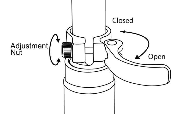
Fig. 9: Opening and adjusting a quick release.
WARNING |
|
| CAUTION: Do not raise seat post beyond the minimum insertion line. To maintain rider safety, at least 2 1/2″ of seat post must be in the frame at all times (Fig. 8) | |
-
- Open the seatpost quick release lever (Figs. 9 & 10).
- Insert the seatpost into the seat tube to a sufficient depth so that the minimum insertion line is no longer showing (Fig. 10).
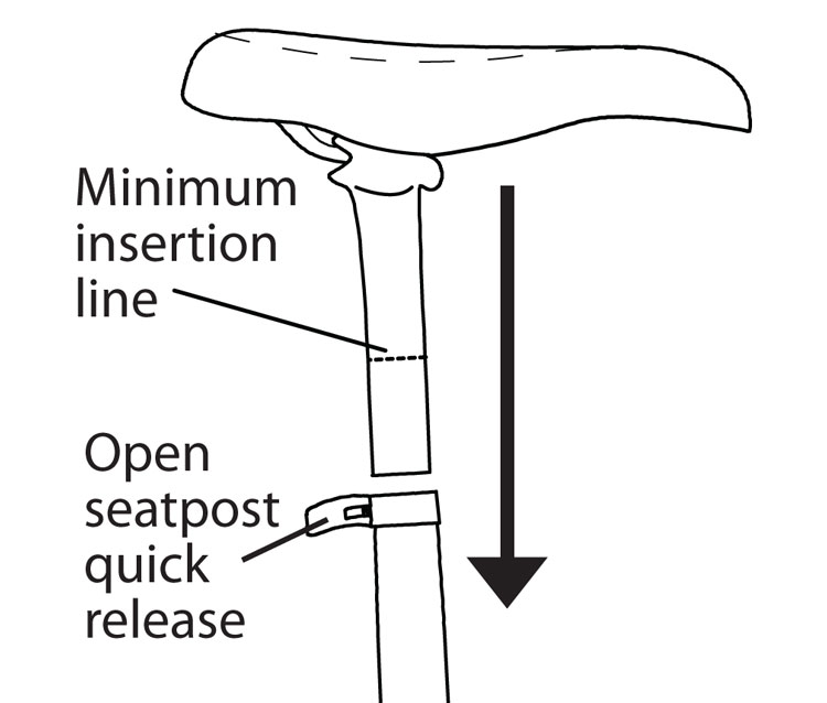
Fig. 10 Insert seatpost beyond minimum line.
- When you are satisfied with the height of the seatpost, close the seatpost quick release lever. The tightness of the lever is adjusted by rotating the adjustment nut opposite the quick release lever. Turn the nut by hand to adjust the tension while holding the lever stable (Fig. 9).
- The lever is securely tightened when it leaves an imprint on the palm of your hand from pushing it closed.
- Once the lever is securely closed, you should not be able to move it unless you open it again. If you can move the seat up and down or side to side with the quick release lever in the closed position, repeat the seatpost installation process from step 3. Repeat until the seat cannot be moved when the quick release lever is closed.
- If you have adjusted the nut too tightly and cannot push the lever to the “close” position, open the quick release lever again and turn the adjusting nut 1/4 turn counterclockwise. Continue with Step 3.
- Adjust for comfort of the rider. The saddle is properly adjusted when you can sit on the saddle, and with your knee only slightly bent (approximately 15º), reach the pedal at its lowest point with the ball of your foot.
Installing the Pedals
You will find a single pedal in your small parts box. This pedal is stamped “R” for Right. The left pedal should be located on the bike and clearly market “L” for Left, on the ends of the axle shaft to differentiate between right and left.
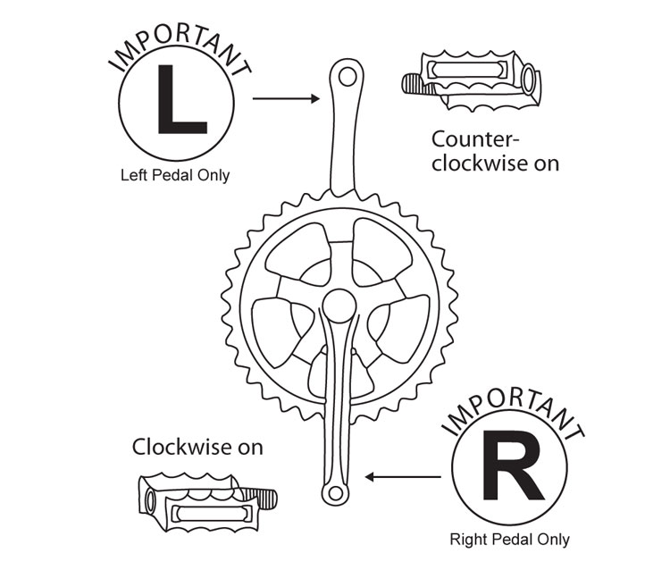
Fig. 11: Install the pedals
CAUTION |
|
| Do not try to insert the wrong pedal into the crank, as it will strip the crank threads. Always check that the pedals are securely tightened before riding. | |
- Align the right pedal axle into the threaded hole in the right crank arm and secure it in the crank by hand. The right hand side of the bicycle is the side of the bicycle with the chain.
- The right pedal is installed by turning the pedal axle clockwise. The left pedal is installed by turning its axle counterclockwise (Fig. 11).
- When hand-tight, use the 15mm pedal wrench (in small parts box) to tighten the pedals to 350-380 lb•in (40.2-42.9 N•m). Each pedal should be tight against the crank arm.
Installing the Handlebars
For some models, the handlebars are shipped off the bike. If so:
- Using the provided hex wrench, remove the two screws (or four, depending on model) holding the stem clamp in place (Fig. 12).
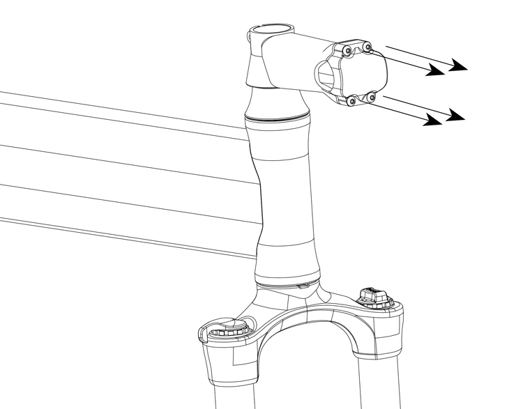
Fig. 12: Remove the stem clamp.
2. Place and center handlebars within the stem (some have centerline marks), and replace screws (Fig. 13).
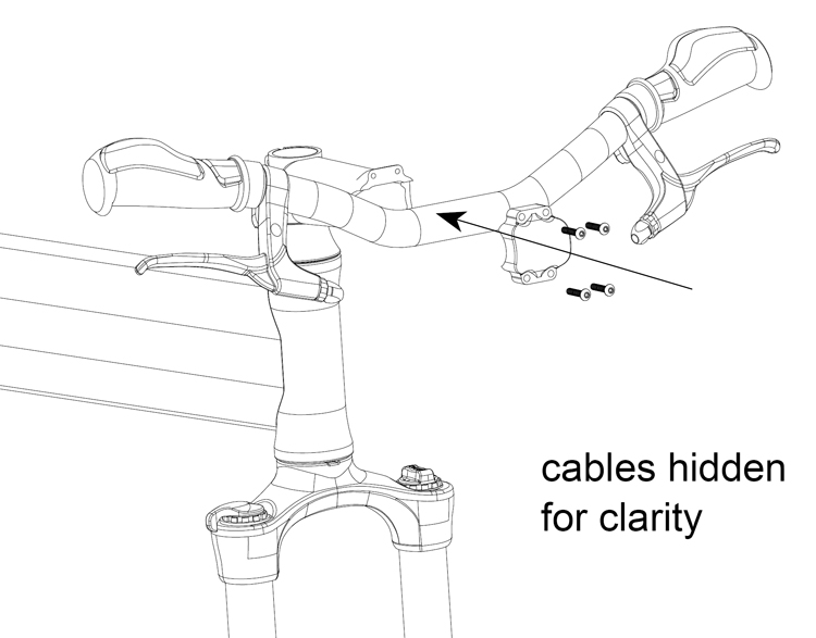
Fig. 13: Replace and center handlebars.
3. Tighten with the provided hex wrench (Fig. 14) to proper torque (page 36). Make sure that the gap between the stem is roughly the same on the top and bottom (Fig. 15, a), and the handlebars are at a comfortable riding angle (Fig. 15, b).
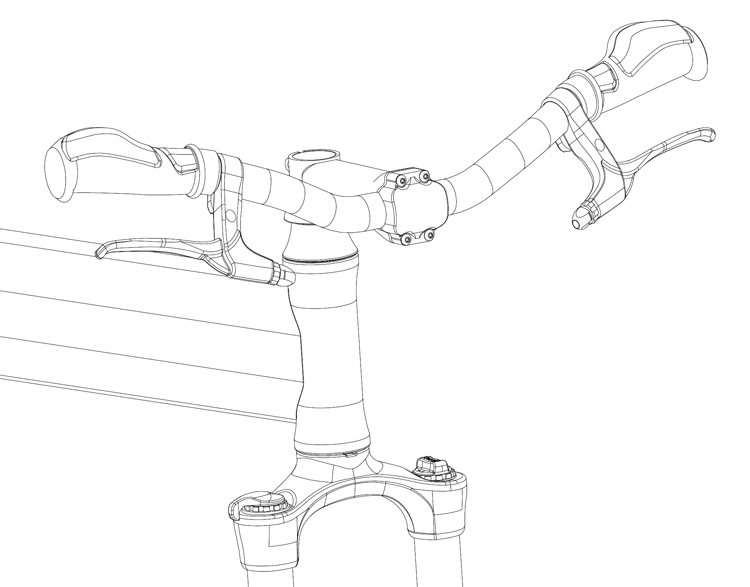
Fig. 14: Tighten screws.
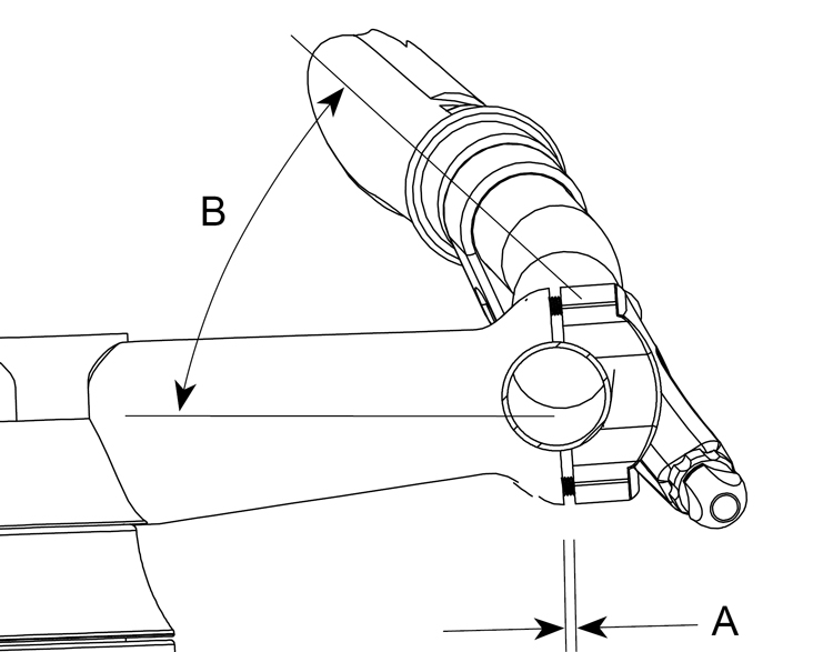
Fig. 15: Set at comfortable angle.
To complete the assembly of your Montague bicycle, continue with the instructions provided in the next sections, Installing Front Fender, Operating RackStand, and Unfolding Your Montague Bicycle.
Installing the Front Fender
To Install the Front Fender
Bikes that come with RackStand also include a matching front fender. This fender must be installed upon assembly.
Pavement Bikes
- Remove the nut from the rear of the front fork (Fig. 16). Depending on the model, the mating screw may be part of the caliper brake assembly or a bare screw.
- Position the fender on the back side of the fork and reinstall the nut so that it passes through the slotted fender mount. Tighten (Fig. 16).
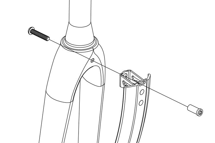
Fig. 16: Pavement bike fender installation.
Mountain Bikes
- Remove the screw from the rear of the front fork. Some forks allow the screw to thread directly into the fork crown (Fig. 17), while some pass through to a nut on the front of the fork (Fig. 18).
- Position the Fender on the back side of the fork and reinstall the bolt so that it passes through the slotted fender mount. Tighten it into the fork (Fig. 17), or the nut on the front of the fork if applicable (Fig. 18).
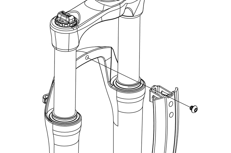
Fig. 17: Fender installation on mountain bike with threaded fork mount.
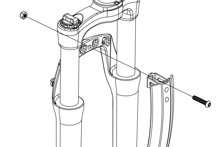
Fig. 18: Fender installation on mountain bike with non-threaded fork mount.
Operating RackStand™
Convert from Rack to Stand
- The RackStand is shipped in the stand position. To convert to a rack, lift the rear of the bike and rotate the RackStand up until it locks into the latch under the seat, making an audible “click” sound. (Figs 19.a & b).
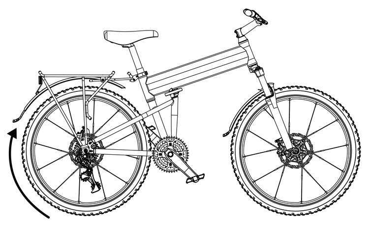
Fig. 19.a: Rotating RackStand up.
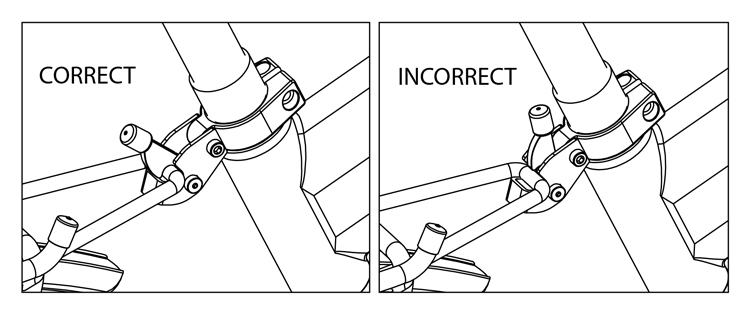
Fig. 19.b: Correct (fully locked) and incorrect RackStand latch position.
Convert from Rack to Stand
1. Prior to removing the front wheel or folding the bike, lift up the latch under the seat to release the RackStand (Fig. 20).
2. The RackStand will rotate down until it hits the ground (Fig. 21).
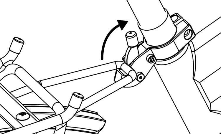
Fig. 20: Opening RackStand latch.
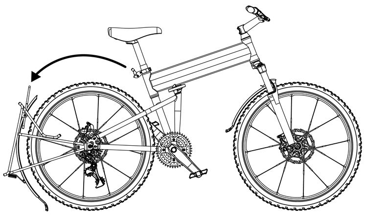
Fig. 21: Rotating RackStand down.
3. Lift the rear of the bike to allow the RackStand to finish rotating under the rear wheel (Fig. 22).
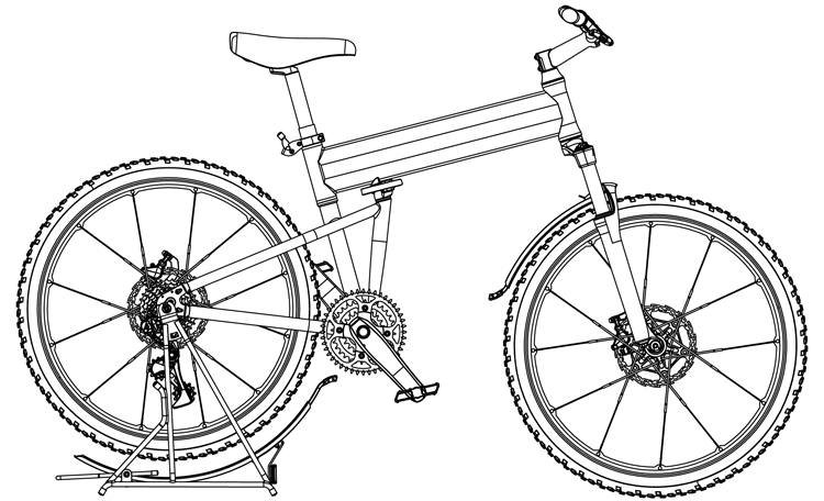
Fig. 22: RackStand in down position.
4. The bike can now be more easily folded in this position, or the RackStand can be used as a kickstand or work stand.
Unfolding Your Montague Bicycle
WARNING |
|
| Failure to properly lock the quick release levels for the wheels, seatpost, frame or brakes can result in loss of control and may result in serious injury or death. | |
Great care should be taken when locking the quick release levers on the bicycle. After reading this manual if you do not fully understand how to operate the quick release levers, ask a bicycle dealer for assistance, or call Montague’s Customer Support Team at +1 617-491-7200. Do not ride your bicycle without all quick releases securely locked.
There are 7 different types of quick release found on your Montague bicycle They are as follows:
- CLIX® Wheel Release System. See pages 28-30 (Attaching the Front Wheel). Not on models prior to 2007.
- The DirectConnect™ frame quick release. See Adjusting the Frame Quick Release, page 27.
- The seatpost quick release. See pages 21 & 38.
- The rear wheel quick release lever. See pages 44-45. Not on all models.
- The caliper brake release lever (Fig. 33, page 31). Not on all models.
- Octagon® quick release (Fig. 47, page 37). Not on all models.
- RackStand™ quick release (Fig. 20, page 25). Not on all models.
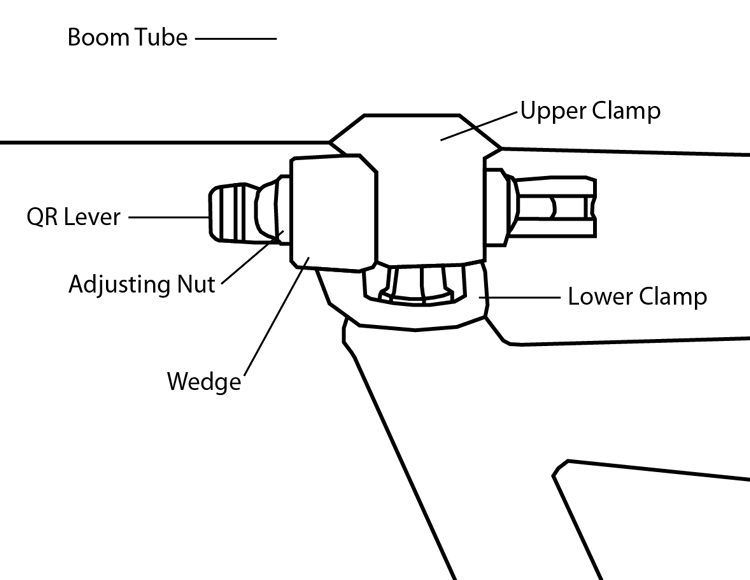
Fig. 23: Parts of the DirectConnect™ frame quick release (shown in closed position above).
To Unfold your Bike:
- Undo the Velcro strap holding the handlebar to the rear wheel. It should be rolled back onto itself around the handlebar while the bike is unfolded.
- Ensure the frame quick release is in the open position (Fig. 36 page 32).
- Place the rear wheel on the ground, grasp the rear wheel with one hand and the handlebar stem with the other and unfold the bike (Fig. 24).
- When the frame is almost completely unfolded, firmly pull the frame straight. The spring loaded Wedge will “click” into place over the Upper Clamp of the frame (Fig. 23).
- Make sure the Wedge is completely engaged. It should hold the Upper and Lower Clamps together, and the frame should no longer fold (Fig. 23).
- Secure the frame quick release lever by closing the quick release. It should point forward on the right side of the bike and rest against the Wedge when closed. (Figs. 23-26)
Note: When closing, if the quick release lever does not leave an imprint on the palm of your hand, refer to Adjusting the Frame Quick Release below. (Fig. 26)
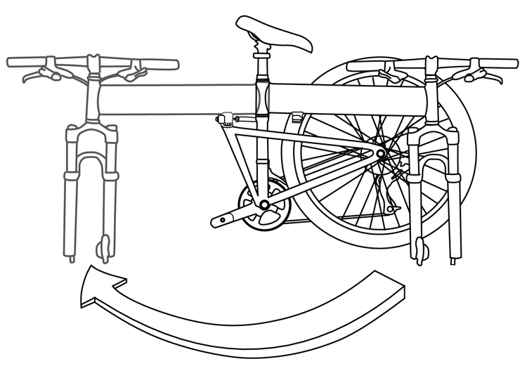
Fig. 24: Unfold the frame.
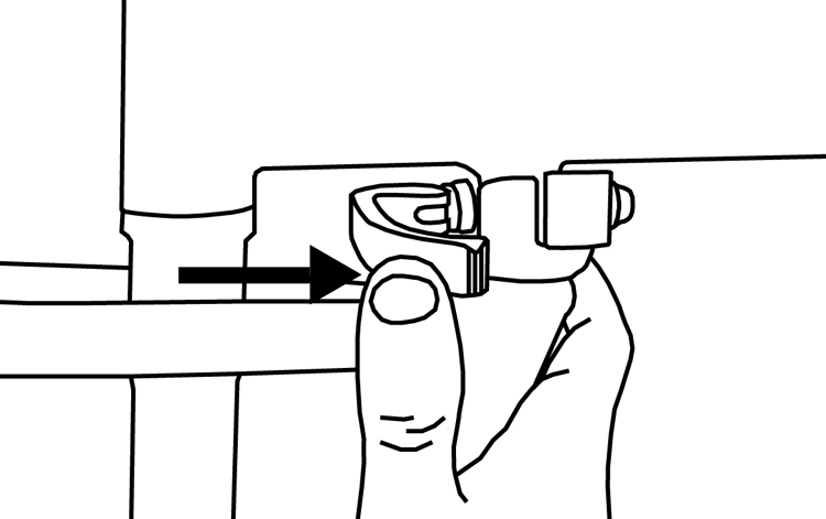
Fig. 25: Close frame quick release.
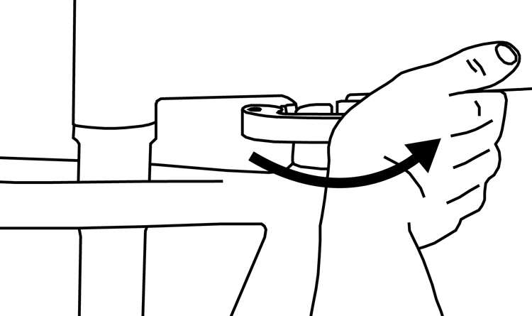
Fig. 26: QR should leave imprint on palm of hand.
Adjusting the Frame Quick Release
If the frame quick release becomes loose or does not leave an imprint on your palm when closing the lever, the quick release may need to be adjusted. To adjust the quick release.
- Make sure your bicycle is in the unfolded position with the frame quick release Wedge properly seated over the Upper Clamp (Fig. 23).
- Open the quick release lever so the lever is pointing toward the rear of the bike. Tighten the adjusting nut 1/2 turn.
- Close the lever. If there is too much resistance for you to be able to close the lever, open, and turn the adjusting nut counter-clockwise 1/4 turn and try to close again.
- The quick release is securely closed when it leaves an imprint on the palm of your hand from moving the lever into the closed position. Make sure the word “close” is visible and that the lever is pushed fully to the closed position.
WARNING |
|
| Great care should be taken when locking the quick release levers on the bicycle. If you do not fully understand how to operate the quick release levers, ask a bicycle dealer for assistance, or call Montague’s Customer Support Team at +1 617-491-7200.
DO NOT RIDE YOUR BICYCLE WITHOUT ALL QUICK RELEASES SECURELY LOCKED |
|
Front Fender
Some bike models come with a front fender. When unfolding it must be moved from the down position to the up position.
- Rotate the fender to the up position, slide it in toward fork, rotate screw clockwise to lock in place (Fig. 27).
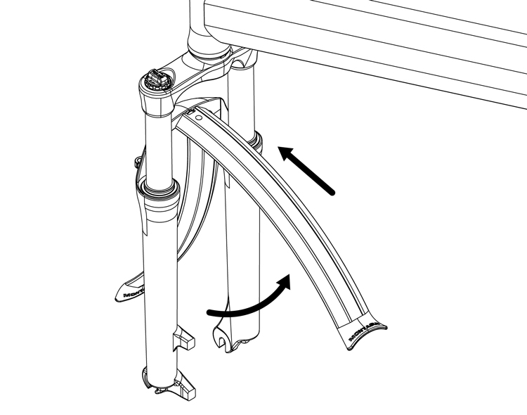
Fig. 27: Rotate, slide in, and tighten fender in place.
Attaching the Front Wheel
WARNING |
|
| Improper installation or improper use of the quick release system can allow the wheel to WOBBLE or DETACH from the bicycle causing you to crash. Read and follow these instructions to properly install and use this product to reduce your chance of SERIOUS INJURY or DEATH. | |
Once the bicycle frame is in the unfolded position with the frame quick release locked, you will need to attach the front wheel. The front wheel on your bicycle is attached via the CLIX® Wheel Release System.
WARNING |
|
| DO NOT change or swap wheels between different bicycles. Your CLIX quick release wheel may not engage another bicycle’s fork correctly, causing an accident. Your CLIX quick release wheel is not compatible with all forks. | |
-
- Make sure that the CLIX quick release is in the open position. (Fig. 28.a)
- Lower your fork onto the wheel hub so that the fork dropouts are resting on the hub axle. (Fig. 28.b). NOTE: For forks with angled dropouts (Fig. 31.a): The dropouts are designed to slide past the cup and adjusting nut and click onto the hub axle.

WARNING
DO NOT spin the CLIX quick release level to secure the wheel. Spinning the lever in the open position (like a wing nut) will not fully secure the wheel to the bike, even if it appears to be tight. - For forks without angled dropouts (Fig. 31.b): Squeeze the cup and CLIX quick release lever (Fig. 28.b) together like a syringe to allow the fork dropouts to rest on the hub axle.
- Close the CLIX quick release lever as shown in (Fig. 28.a). The mechanism should emboss the fork ends when closed to the locked position. Check that the word “close” is visible and that the lever is pushed fully to the closed position. The CLIX quick release lever is securely closed when it leaves an imprint on the palm of your hand from moving the lever into the closed position. Make sure the lever is positioned adjacent to the fork leg so it will not catch on any passing objects.
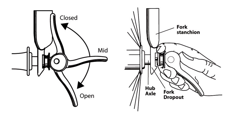
Fig. 28.a: Closed, Mid, Open positions & Fig. 28.b: Install the wheel on the fork.
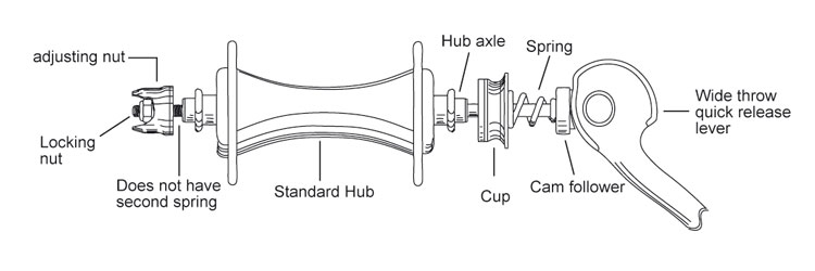
Fig 29.: The CLIX® Wheel Release System.
- Before riding, lift the front of the bicycle so that the front wheel is off the ground and give the top of the tire a few sharp downward strikes (Fig. 30). The wheel should not wobble or come off.
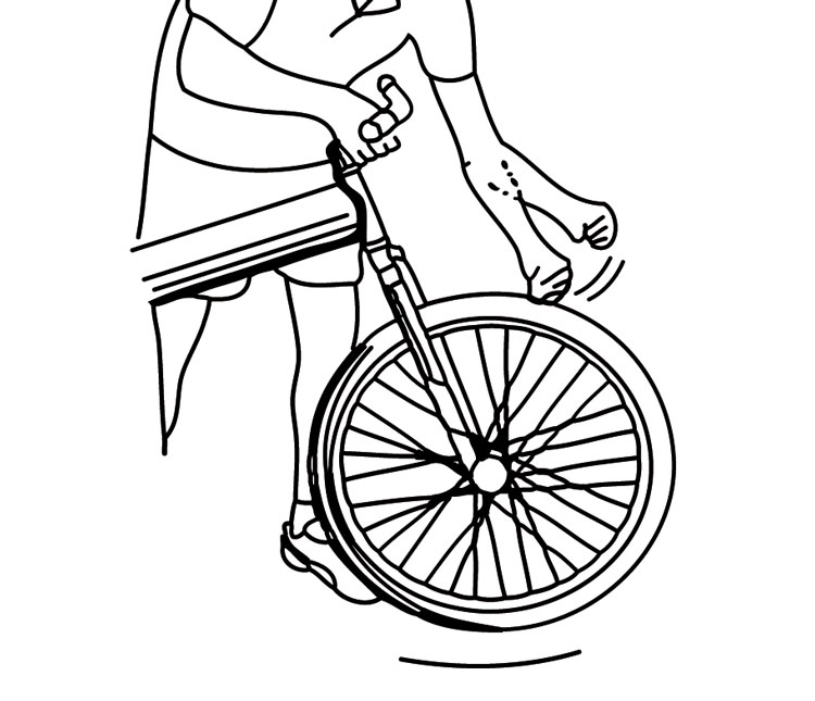
Fig. 30: Strike the wheel in a downward motion.
This does not guarantee that the CLIX quick release lever has been adequately tightened. If you are uncertain as to whether the CLIX quick release is tightened correctly, see the following information on Adjusting Your Front Wheel Quick Release, or bring your bike to your local bike shop.
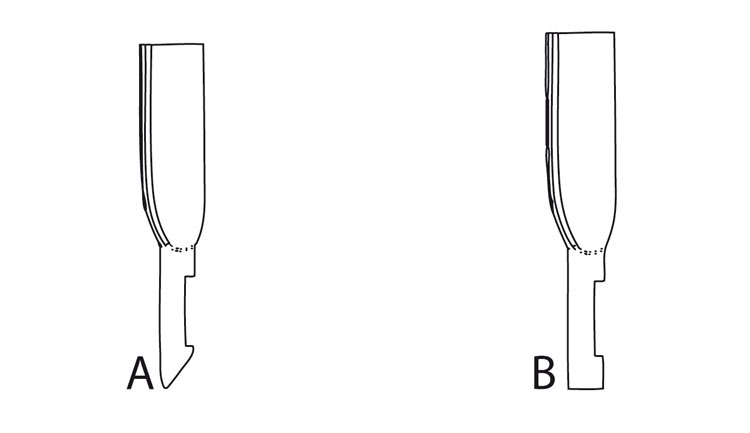
Fig 31.a: Angled dropout & Fig 31.b: Standard dropout.
Adjusting your CLIX Front Wheel Quick Release
If your CLIX front wheel quick release is too loose or needs to be adjusted:
- Open and close the quick release lever with your right hand while gradually tightening the adjusting nut with your left hand. Continue tightening the nut until you feel resistance on the lever at the mid point (Fig. 28.a) of its travel.
- If there is too much resistance, turn the adjusting nut counter-clockwise 1/4 turn and try to close again.
- The CLIX quick release lever is securely closed when it leaves an imprint on the palm of your hand from moving the lever into the closed position. Make sure that the word “close” is visible.
- Now that the correct tension has been set with the CLIX quick release lever in closed position, tighten the locking nut with 8mm socket wrench until it is next to, but not tight against, the adjusting nut (Fig. 29, page 29).
Securing the Front Brake
Depending on the model you have purchased, your bike will feature one of three kinds of brake:
- Disc brake (Fig. 32)
- Caliper brake (Fig. 33)
- V-brake (Fig. 34)
WARNING |
|
| Always inspect the brakes before riding to be sure they are functioning properly. If you are not comfortable with the assembly instructions, please see a bicycle dealer. Brakes that are not properly adjusted may result in loss of control and serious personal injury or death. NEVER ATTEMPT TO RIDE A BICYCLE WITHOUT PROPERLY FUNCTIONING BRAKES. | |
Consult the following information to properly install your brakes.
Disc Brakes (Fig. 32)
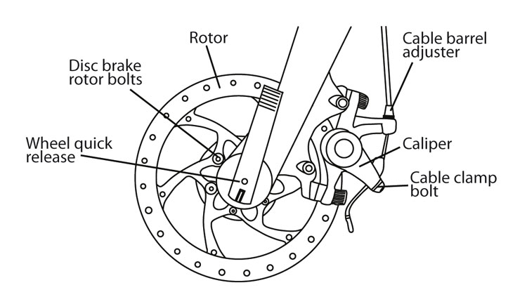
Fig. 32: Disc Brake
Disc brakes should come from the factory pre-adjusted to the correct braking specifications.
To attach the front wheel on a disc brake equipped bike, align the wheel rotor with the slot in the disc brake caliper attached to the left hand fork stanchion.
Once the rotor is aligned with the caliper slot, review Attaching the Front Wheel on page 28 in order to properly secure the front wheel quick release.
If your front or rear disc brake needs to be adjusted or does not apply adequate stopping power to the wheel, it may need to be adjusted. Be sure to squeeze the brake levers to ensure that the brakes are secured in place and functioning properly before riding. For adjustment instruction, please see Brakes on pages 42-43.
Note: When installing the front wheel on a disc brake equipped model, the disc brake rotor is lined up between the brake pads in the caliper slot. If the pads are knocked out of place, the rotor may not go into the caliper slot. Reset the pads before attempting to install the wheel.
Caliper Brakes (Fig. 33):
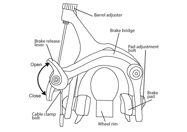
Fig. 33: Caliper brake release lever.
Once the wheel is installed, caliper brakes are engaged by moving the brake release lever to the “close” position (see Fig. 33). To release a caliper brake, move the brake release lever into the “open” position. Be sure to squeeze the brake levers to ensure that the brakes are secured in place and functioning properly before riding. For caliper brake adjustment, see Brakes on pages 42-43. Before riding, always check to make sure the brake release lever is in the closed position.
V-Brakes (Fig. 34)
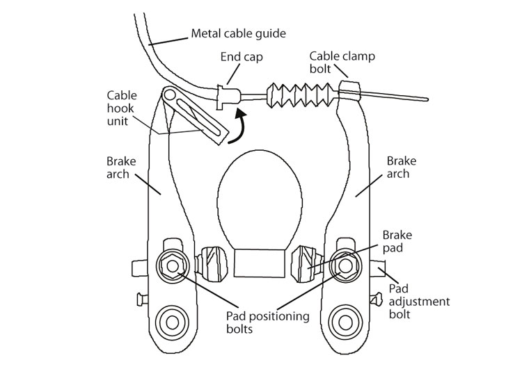
Fig 34: Assembly of V-Brake.
To attach a V-brake:
- Use one hand to pinch the brake arches together and level the cable hook unit.
- With the other hand, squeeze the end cap into the cable hook unit.
- Release the brake arches and the hook unit and end cap should lock into place.
- Squeeze the brake lever a few times to ensure the brakes are secured in place and working properly.
Brakes and Gear System: The brakes and gear system are factory set. However, new brake and gear cables may stretch. Therefore, please check brakes and gear system each time before riding your bicycle. If a problem is identified, refer to the Brakes section of this manual (pages 42-43) or bring your bike to your local dealer. Do not ride the bike with non-functioning brakes.
Folding Your Montague Bicycle
- Standing on the chain side of your bike, set the front brake to the open position.
- For caliper equipped bikes, see Fig. 33, page 31.
- For V-brake equipped bikes, see Fig. 34, page 31.
- For disc brake equipped bikes continue on to the next step.
- Open the CLIX front wheel quick release lever, then squeeze the cup and quick release lever together using the same motion used when operating a syringe (Fig. 28.b page 28) while removing the wheel (Fig. 35).
- Lower the seat. (Fig. 10 page 21).
- Open the frame quick release lever (Fig. 35).
- With your thumb, press and hold the knurled lever inward. This opens the quick release clamp. (Fig. 36).
- While holding the quick release open with one hand, grasp the handlebars with the other and turn them away from you (Fig. 37).
- Pull the boom tube of the bike toward you and fold the bike in half (Fig. 37).
- If done correctly, the bike should resemble Fig. 38 with the handlebars secured between the rear wheel and the boom tube.
- Reattach the Velcro strap from the handlebars to the rear wheel.
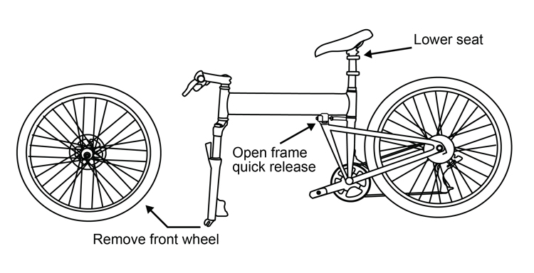
Fig. 35: Remove the front wheel & lower seat.
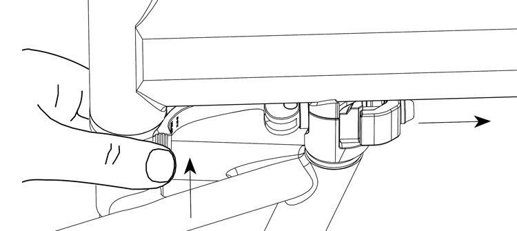
Fig. 36: Press and hold, quick release clamp opens
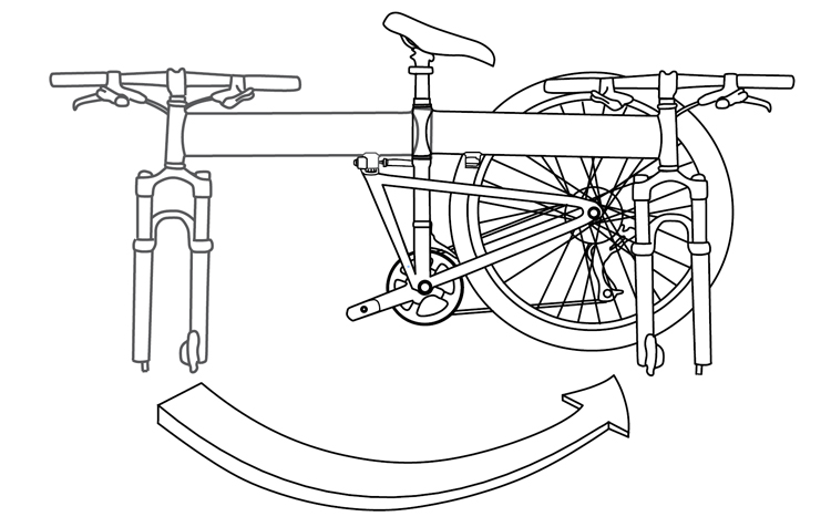
Fig. 37: Fold the bike frame in half.
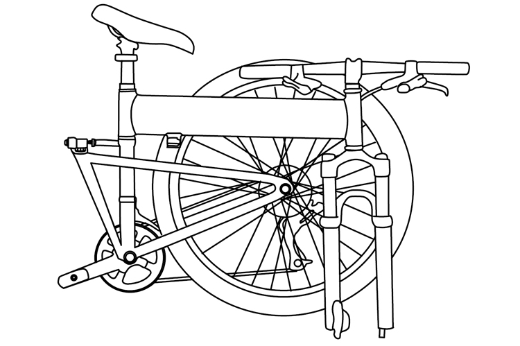
Fig. 38: Folded bike.
Installing RackStand™
To Install RackStand:
- Remove the original rear wheel quick release by unscrewing the end nut. Replace with RackStand quick release with spacers in order shown (Fig. 39). Tighten to proper tension (page 44).
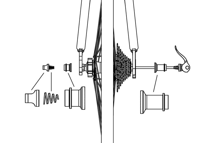
Fig. 39: Installing RackStand quick release
- Place RackStand upside down (stand position) on the floor, with tail facing the front of the bike (Fig. 40).
- Position the rear of the bike so it is resting on the tabs of the new quick release as shown. (Fig. 40).
- Open the QR lever and lower bike into the RackStand slots (Fig. 41).
- Close quick release lever and rotate RackStand up to the riding (rack) position. Ensure it is locked into mating latch (Fig. 42).
Fig. 40 Positioning RackStand (wheel not shown for clarity).

Fig. 41: Lowering bike into RackStand dropouts.

Fig. 42: Rotate RackStand and lock in place
After attaching RackStand to your bike, the rear fender may need to be adjusted.In the folded position, the weight of the bike rests on the “tail” of the fender. For the folded bike to rest at the correct angle, the position of the fender tail can be extended or shortened.
To Adjust RackStand:
- Loosen the two bolts holding the tail of the fender in place (Fig. 43).

fig. 43: Loosen fender tail bolts.
- Slide the fender tail to a length that will hold the folded bike with the seat tube perpendicular to the ground (Fig 44). The fender will need to be longer for a mountain bike than a pavement bike.
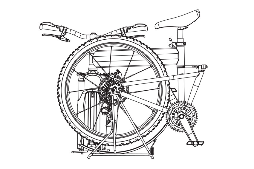
Fig. 44: Correct bike position with the Rackstand.
- Re-tighten the bolts to secure the fender tail in place (Fig. 43).
Proper Maintenance And Adjustment
WARNING |
|
| DO NOT attempt to perform any adjustments while riding your bike. | |
This chapter lists instructions for adjustment of the parts of a bicycle. After a repair, examine the bicycle as shown in the Before Each Ride Checklist on page 10. This manual is not intended to be a repair manual. If you are unsure about adjusting your bicycle or have any questions about adjusting your bicycle, transport it to your local dealer for adjustments and repairs.
WARNING |
|
| A bicycle that malfunctions could decrease your control and cause you to fall. Fully examine all of the bicycle before each ride. If there is a problem, do not ride the bicycle, but take it to your local bike dealer for inspection and repair. | |
Torque Specifications
Torque is a measure of the tightness of a screw or bolt. Use a torque wrench to make sure you do not apply too much torque, which can cause damage to or break the part. However, a fastener that is too loose can also cause damage. After you use the torque wrench, examine the function of the part with the tests in this section. If a part does not have the correct function when it is tightened to the recommended torque, tranport your bicycle to your dealer for repair.
WARNING |
|
| Incorrect torque can cause damage or break a part. Use a torque wrench to correctly tighten a part, or transport the bicycle to your dealer for service. | |
It is important to use only genuine replacement parts with dimensions identical to the original components on your bike. The Montague frame quick release and the Octagon stem assembly are both safety-critical components. Only replace the frame quick release and the Octagon stem with a genuine part sourced from Montague. Do not switch your fork as your CLIX quick release wheel is not compatible with some forks.
If you replace the crank or tires with different models, you should use caution as there is a possible reduction of toe-clearance and the possibility of contact with the ground may be increased.
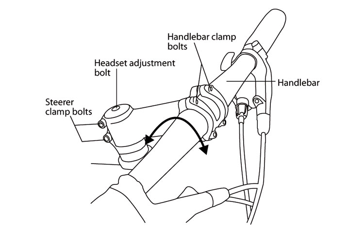
Fig. 45 Handlebar bolts on threadless stem
Handlebars
To rotate angle of your handlebar:
- Decrease the tightness of the handlebar clamp bolts on the stem (Fig. 45).
- Twist the handlebar by rotating it forward or backward. Make sure it remains in the center of the stem (Fig. 45).
- Tighten the handlebar clamp bolts on your type of stem: Welded stems: 100-120 lb•in (11.3-13.6 N•m). Forged Stems: 150-180 lb•in (17-20.3 N•m).
Stems
There are three types of stems:
- Direct Connect (Fig. 45)
- Quill-type (Fig. 46)
- Octagon® Hand Height Adjustable Stem (Fig. 47)
Some stem models allow for height adjustment. Please read the following instructions to determine if your stem is height adjustable.
Threadless stem height adjustment:
Handlebar height on bicycles with direct connect stems cannot be adjusted as they are. Please refer to your local dealer for options regarding handlebar height adjustment.
Minimum spacers with a threadless stem:
Bicycles with aluminum steerer tubes should have at least one 5mm spacer under the threadless stem (Fig. 45).
WARNING |
|
| Incorrect or missing spacers can cause damage to the steerer of the fork, possibly causing it to break. If the steerer breaks, you could fall. | |
Threadless stem alignment:
- Decrease the tightness of the steerer-clamp bolts two to three turns (Fig. 45).
- Align the stem with the front wheel
- Tighten the steerer-clamp bolts to 100-120 lb•in (11.3-13.6 N•m).
To align or adjust a quill type stem:
WARNING |
|
| A quill stem that is too high can cause damage to the bicycle, decrease your control, and cause you to fall. Make sure the minimum insertion mark is inserted in the frame (Fig 46). | |
- Decrease the tightness of the quill expander-bolt two to three turns (Fig. 46).
- The stem is held by the stem wedge. To decrease the tightness of the stem wedge, tap the top of the expander bolt with a mallet that has a wood or plastic face.
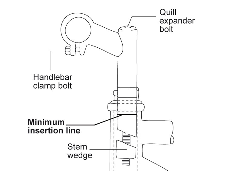
Fig. 46: Quill stem parts
- Adjust the handlebar to the necessary height. Take note of the minimum insertion point as marked on the stem quill. Never raise the stem beyond the minimum insertion point (Fig. 46). A minimum of 70mm of the stem should always be in the frame.
- Tighten the expander bolt to 120 lb•in (13.6 N•m).
Handlebar height adjustment with the Octagon® Adjustable Stem:
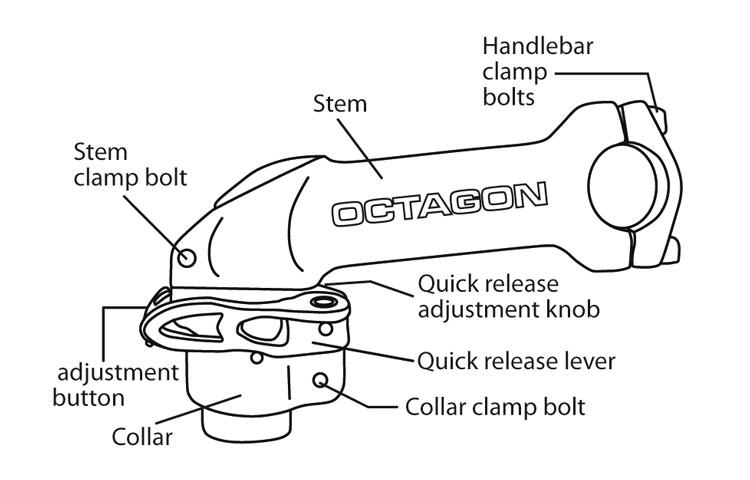
Fig. 47: Octagon® stem parts
The Octagon® height adjustable stem allows you to raise and lower your handlebars without the use of any tools.
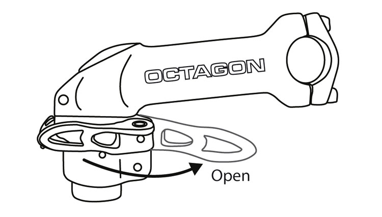
Fig. 48: Open quick release lever.
This system is only on select Montague models. To change the height of your handlebars with the Octagon® stem follow these steps:
- Open the collar quick release lever (Fig. 48).
- Depress the adjustment button with one hand while grasping the stem with the other. While continuing to hold the adjustment button, raise the stem to the desired height (Fig. 49).
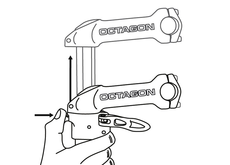
Fig. 49: Push adjustment button and raise stem.
- Once the desired stem height is reached, release the adjustment button and try to move the stem higher or lower. This will lock the stem into position.
- Close the quick release lever. The tightness of the lever is adjusted by rotating the adjustment nut opposite the quick release lever. Turn the nut by hand to adjust the tension while holding the lever stable (Fig. 50).
- The lever is securely tightened when it leaves an imprint on the palm of your hand from pushing it closed.
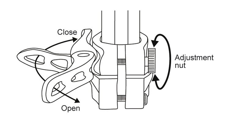
Fig. 50: Octagon® quick release adjustments.
- Once the lever is securely closed, you should not feel any looseness or movement in the handlebars or stem. If you can move the handlebars from side to side or feel any looseness with the quick release lever in the closed position, repeat the Octagon® quick release adjustment process from step 4. Repeat until the handlebars cannot be moved when the quick release lever is closed.
- If you have adjusted the nut too tightly and cannot push the lever to the “close” position, open the quick release lever again and turn the nut 1/4 turn counterclockwise. Continue with Step 4.
Note: The collar clamp bolt and the stem clamp bolt should be tightened to 88 lb•in (10 N•m).
WARNING |
|
| If you complete these adjustments and the quick release is tight, yet the handlebars feel loose, do not ride your bike, but take it to your local dealer for inspection and adjustment. | |
For more information about the Octagon® height adjustable stem, visit www.octagoncycles.com.
Adjust headset tension with the Octagon Adjustable Stem:
An Octagon equipped bike does not use a traditional star nut and top cap to set headset pre-load tension. Follow these steps to set tension.
1. Open the collar quick release lever (Fig. 48)
2. Loosen the bolt on the Octagon collar and remove the Octagon system from the fork steerer tube.
3. Depress the brass button on the bottom of the vertical section of the Octagon, slide it up and remove it from the collar.
4. Re-install the collar onto the fork steerer tube.
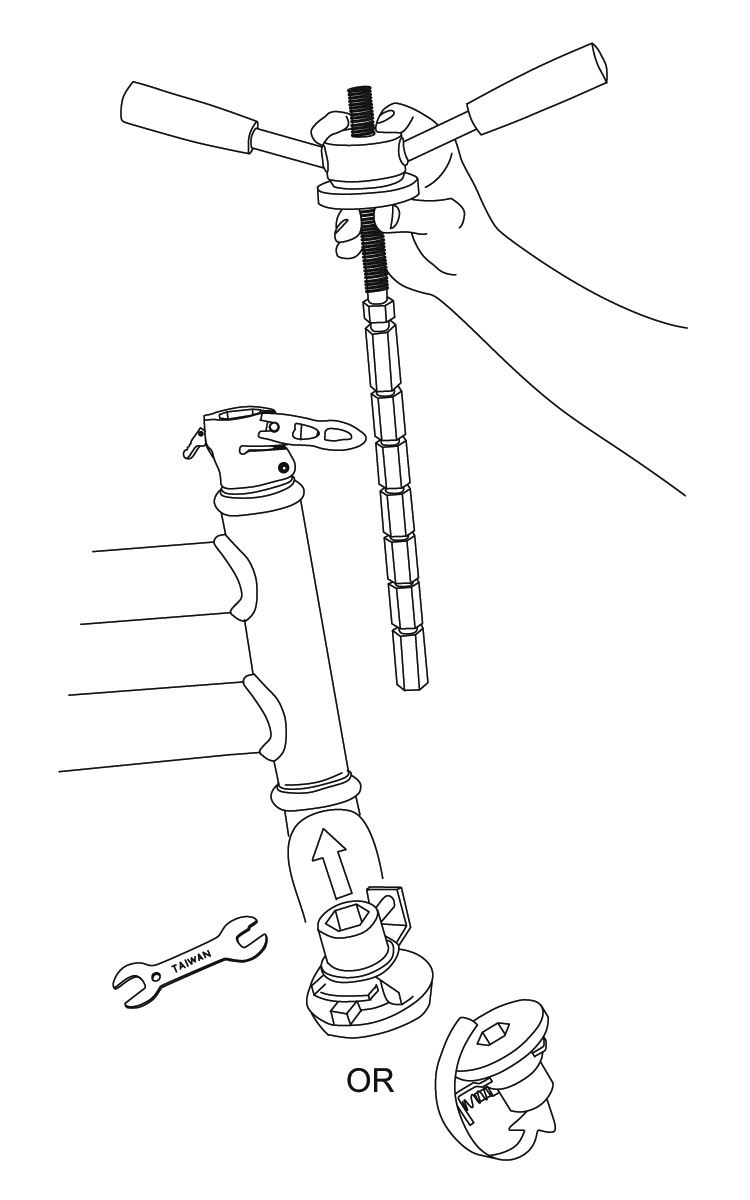
Fig. 51a: Headset press into Octagon and fork
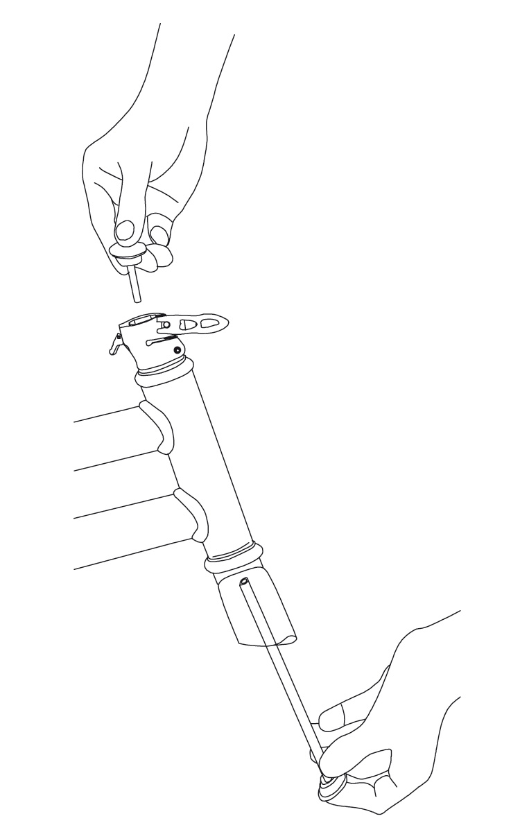
Fig. 51b: Headset tool into Octagon and fork
5. A traditional headset press tool or a BMX style headset adjustment tool can be used to compress the headset bearings. Slide the tool through the Octagon collar and steerer tube of the fork while on the bike and secure the bottom of the tool (Fig. 51a & 51b).
6. Tighten the headset press or headset tool until there is no side to side movement in the headset bearings.
7. While pressure is being applied to the headset bearings, use a torque wrench to tighten the bolt on the Octagon collar to 88 lb•in (10 N•m). (Fig. 52)
8. Remove the headset press or headset tool from the bike.
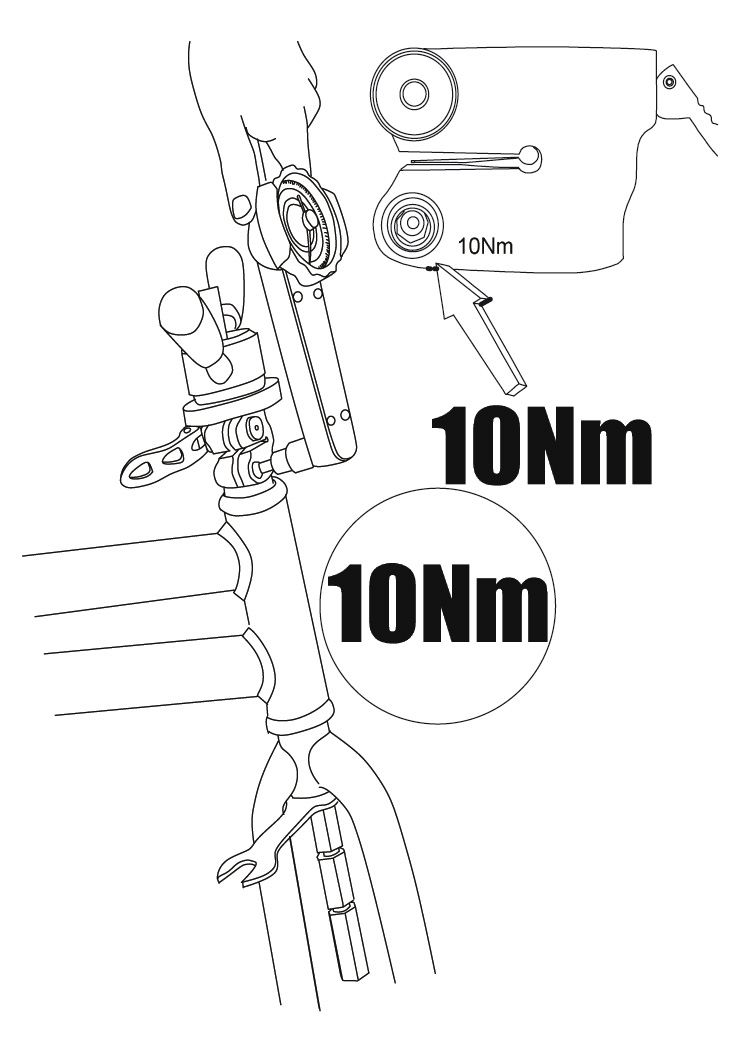
Fig. 52: Tighten Octagon collar bolt.
9. Re-install the vertical section of the Octagon in the collar by depressing the brass button on the bottom and sliding it into the collar. The scale on the Octagon vertical should be facing the right side of the bike.
10. Follow instructions for Handlebar height adjustment to set the height and lock the Octagon vertical in place (pg. 37).
WARNING |
|
| If you complete these adjustments and the quick release is tight, yet the handlebars feel loose, do not ride your bike, but take it to your local dealer for inspection and adjustment. | |
Seat (Saddle) Adjustments
WARNING |
|
| If you ride a saddle that is not adjusted correctly or one that does not correctly support your pelvic area, it can cause injury to your nerves and blood vessels. If your saddle causes pain or numbness, adjust the saddle position or speak to your dealer about a saddle that is more comfortable. | |
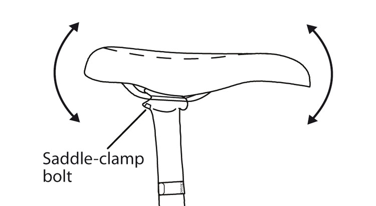
Fig. 53: Saddle bolts and adjustments.
Saddle angles can be adjusted to meet your preferences. It is recommended that you first try to ride with the top of the saddle parallel to the ground. The saddle can also be moved forward or rearwards along the seatpost to adjust the distance from the handlebar.
To adjust the angle of the saddle:
- Decrease the tightness of the saddle-clamp bolt (Fig. 53) until the saddle can be moved.
- Put a straight edge, bubble level or ruler across the top of the saddle to better see the angle of the saddle.
- Adjust the saddle and tighten the saddle-clamp bolt for your type of seatpost:
- One bolt that uses a 13 or 14 mm open-end wrench: 180-220 lb•in (20.3-24.9 N•m)
- One bolt across the seatpost head that uses a 5mm allen wrench: 120-130 lb•in (13.6-14.7 N•m)
- One bolt that uses a 6mm allen wrench: 150-250 lb•in (17-28.3 N•m)
- Two bolts that use a 5mm allen wrench: 80-120 lb•in (9.6-14.1 N•m)
For saddle height adjustment and seatpost quick release usage, see page 21, Installing the Seatpost.
WARNING |
|
| A seatpost that is too high can cause damage to the bicycle, decrease your control, and cause you to fall. Make sure the minimum-insertion mark (Fig. 10 page 21) is in the frame. | |
Pedals
The right pedal (chainside) is threaded in the standard clockwise to tighten direction. The left pedal is threaded in the opposite direction (Fig. 11, page 22). Tighten pedals into the crankarms to 350-380 lb•in (40.2-42.9 N•m). The adjustment of pedal bearings requires special tools and training. Only a bicycle dealer should attempt these adjustments.
Single Speed Chain Adjustment
To adjust the chain tension on a single speed bicycle:
- Slightly decrease the tightness of the rear wheel axle nut on one side of the wheel, then on the other side of the wheel.
- Slide the wheel rearwards to tighten the chain. Keep wheel centered between seatstays.
- Tighten the rear wheel axle nuts 260-390 lb•in (30-45 N•m).
- Make sure you have correctly attached the wheel by lifting the bicycle, and hitting the top of the tire with a solid blow. The wheel should not be loose or move from side to side (Fig. 30 page 29).
- If the wheel connection fails the test, do the procedures in steps 1-4 again. If you cannot correctly attach the wheel, transport your bicycle to your dealer for repair.
Control Cables
Examine all cables for kinks, rust, broken strands, or frayed ends. Also examine the cable housing for loose wire strands, bent ends, cuts, and worn areas. If you think there is a problem with a cable or housing, replace the cable before riding.
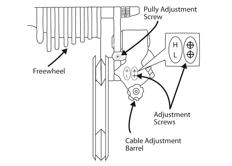
Fig. 54: Rear derailleur parts. View from the rear.
If the gear system is not functioning properly, check to ensure that the rear derailleur follows each shifting command of the right twist shifter/shift lever. Cable stretching could affect the function after some time, so that synchronization may no longer be assured. Position the bicycle in a stand and check and adjust as follows:
- On models with a front derailleur, shift so that the chain is on the middle chainring, by turning the crank forward and shifting the left twist shifter/shift lever.
- Shift the chain to the outermost/smallest rear sprocket by turning the right twist shifter all the way away from you, or moving the right shift lever all the way towards you.
- While turning the crank forward, rotate the right twist shifter or push the right shift lever to the next position.
- The chain should move to the second sprocket quickly and easily. If it stays on the first sprocket, the tension of the shifting cable must be increased (proceed to Step 6).
- If the chain jumps across the second sprocket or if it scratches the third sprocket, the tension of the shifting cable must be decreased.
- Cable tension is adjusted by turning the Cable Adjusting Barrel, which is located at the junction of the cable and the shifter or rear derailleur (Fig. 54). To increase tension, turn the knurled knob counterclockwise, to decrease tension, turn the knob clockwise. Turn until the problem is corrected.
If the tension is adjusted according to the above steps, the chain should follow all shifting commands on the shifters.
If the gear system still does not function properly, please contact a bicycle dealer for assistance.
Front Derailleur Adjustment
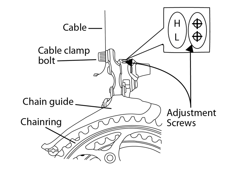
Fig. 55: Front Derailleur Adjustments.
With bicycles that have more than one chainring, the front derailleur makes gear changes.
To adjust small chainring position
- Move the chain to the smallest front chainring and the largest rear gear.
- Decrease the tightness of the cable clamp bolt (Fig. 55) until the cable is free.
- Turn the low-gear adjustment screw (identified with an “L”) until the inner chain-guide of the derailleur is approximately 0.5 mm from the chain.
- Pull on the cable end, and move the left shift lever to the small chainring position.
- On the shift lever, fully turn clockwise the derailleur cable barrel-adjuster.
- Put the cable in the groove found near the derailleur-cable-clamp bolt, pull the cable tight, and tighten the clamp bolt to 44-60 lb•in (5.0-6.8 N•m).
To adjust large chainring position
- Move the rear derailleur to the smallest rear cog.
- Turn the high-gear adjustment screw (identified with an “H”) counterclockwise until it cannot stop the movement of the derailleur.
- Turn the crankarms with your hand. Use the shifter to carefully move the chain to the outside chainring.
- Move the outer chain-guide approximately 0.5mm from the chain.
- Tighten the high-gear adjustment screw until it resists. If you have turned the screw too far, the front derailleur will move to the small chainring.
- Change gears to all the gear combinations. Make sure the chain does not come off when you move the shift lever. Make sure the derailleur cage does not rub on part of the crankarms.
To adjust the middle-gear position with three chainrings
- Move the chain to the largest front chainring and the smallest rear cog.
- Turn the cable barrel-adjuster (on the shifter) to change the cable tension and align the inner cage of the derailleur until it touches the chain.
- Change to all gear combinations to make sure the chain smoothly lines up with all the chainrings.
Internal Gear Systems
These systems change gears with a mechanism that is inside the rear hub. To adjust a Shimano Alfine internal gear hub, please refer to the separate manufacturer’s manual provided.
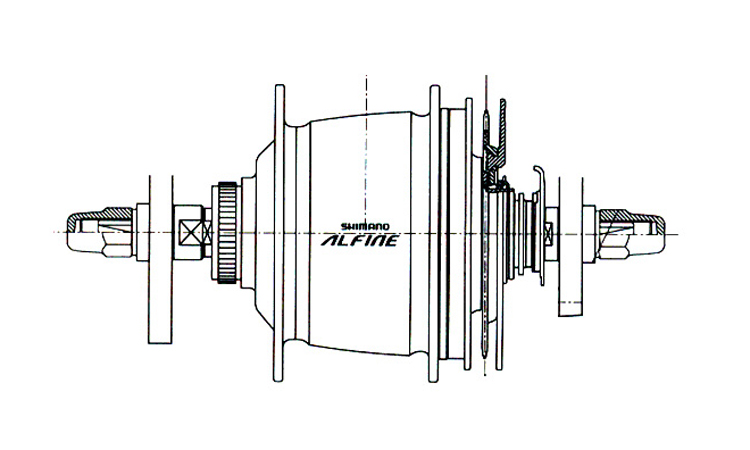
Fig. 56: Alfine rear internal gear hub.
Belt Drive
Some bike models come equipped with a carbon belt drive in place of a traditional chain (Fig. 57). On these bikes an eccentric bottom bracket is used to adjust tension on the belt.
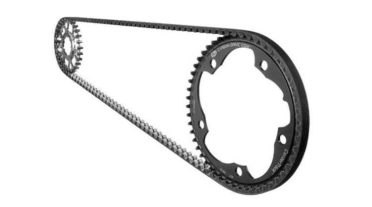
Fig. 57: Gates carbon belt drive.
To adjust belt tension
1. Turn the three bolts A, B1 and B2 on the non-drive side of the eccentric bottom bracket counterclockwise with a hex wrench to
loosen. (Fig. 58)
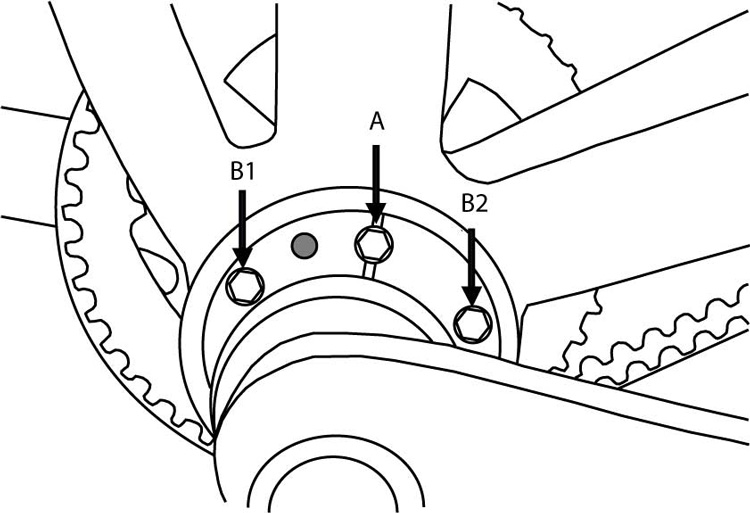
Fig. 58: Eccentric bottom bracket lock bolts
- Re-insert the hex wrench into each bolt and tap the wrench with a hammer to dislodge the bottom bracket.
- The bottom bracket can now rotate freely inside the frame. Turning the bottom bracket counter-clockwise will move the spindle toward the rear of the bike and reduce the belt tension. Turning the bottom bracket clockwise will move the spindle toward the front of the bike and increase belt tension.
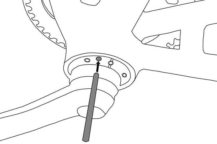
Fig. 59a: Eccentric bottom bracket adjustment
4. To rotate, first slide a 5mm rod through the open hole on the non-drive side of the bottom bracket. A long hex wrench can be used. (Fig. 59a).

Fig. 59b: Eccentric bottom bracket adjustment
5. Push against the rod to rotate the bottom bracket (Fig. 59b). Additional leverage can be achieved with a wrench around the spindle and against the rod.
6. When using a belt in conjunction with an internal gear hub, a tension of 28-40 lbs is recommended. This may need to be adjusted based on the rider size, gear ratio, and power placed on the pedals.
7. On bikes equipped with a Gates Carbon Drive™ belt, tension can be measured using the Carbon Drive™ Krikit tool available from Gates or using their Gates Carbon Drive mobile apps for iPhone® and Android® via their respective application marketplaces.
8.With the desired belt tension, re-tighten the three bolts on the non-drive side of the bottom bracket to 75 – 100 lb•in (8.5-11.3 Nm).
For more information on adjusting a belt drive, please refer to the separate manufacturer’s manual.
Brakes
The brake system on your bike lets you slow and stop. The function of this system is crucial to your safety.
The brake system is not easy to adjust without proper training. It is strongly recommended that only your dealer adjust your brakes. Each month, examine the brake pads for wear. Replace pads if grooves in the pad surface are less than 1mm deep.
To adjust the distance between the rim and brake pads
- Locate the barrel adjuster along the brake cable, either by the brake itself or the brake lever (Fig. 33 page 31).
- Turn the barrel adjuster clockwise to increase brake pad clearance.
- Turn the barrel adjuster counterclockwise to decrease brake pad clearance.
- If the brake pads cannot be adjusted correctly (Fig. 6, page 13), decrease the tightness of the cable-clamp bolt and reattach the cable.
To adjust the alignment of the brakepads on a rim brake
- Decrease the tightness of the pad adjustment bolt or pad positioning bolt (Fig. 33 & 34 page 31).
- Align the brake pads (Fig. 6, page 13). Tighten the brake pad clamp bolts. Caliper: 40-60 lb•in (4.5-6.8 N•m) Direct-pull 70-80 lb•in (7.9-9 N•m).
- Examine your brakes after adjusting them. Pull the levers and make sure the brake pads engage the rim strongly at the proper angle, and the brake pads do not come into contact with the tire (Fig. 6 page 13).
To align a cable actuated disc brake
First adjust the clearance between the right (inside) brake pad and the disc.
- Use a 5mm allen wrench to move the inside pad inward toward the disc rotor till it touches the rotor.
- Back off slightly until the pad does not touch the rotor surface.
Next adjust the clearance between the left (outside) brake pad and the disc.
- Turn the barrel adjuster located on the front brake lever clockwise to move the outside brake pad inward until it touches the rotor.
- Back off slightly (1/4 turn) until the pad does not touch the rotor surface and the wheel spins freely.
If there is contact between the brake pads and rotor after performing the above steps bring your bike to your local dealer for adjustment.
Wheels
WARNING |
|
| When you apply the brake, the brake pads remove material from the rims. If the brakes remove too much material, the rim can become weak and sudden failure can ensue. Examine the rims regularly and replace them when they are worn. | |
Examine tires for worn areas, bulges, and damage. Make sure rims are clean.
WARNING |
|
| Riding with an improperly adjusted wheel quick release can allow the wheel to wobble or disengage from the bicycle, causing damage to the bicycle, and serious injury or death to the rider. | |
Make sure tires are inflated to proper specifications as listed on the sidewall of the tire. If the wear-indicators on the brake surface show the rim is worn, replace the rim. Make sure there are no loose or damaged spokes. If loose or damaged spokes are found, do not ride the bicycle, take it to your local bike dealer for repair.
WARNING |
|
| DO NOT change or swap wheels between different bicycles. Your wheels may not engage the other bicycle’s fork correctly causing an accident. | |
Wheel Installation
As mentioned in the assembly section, Montague bicycles use three different types of wheel attachment devices. Carefully read the instructions for the devices on your bicycle.
- CLIX® quick-release
- Threaded axle and nut (pages 41 and 48)
- Traditional quick-release (rear wheel Fig. 60)
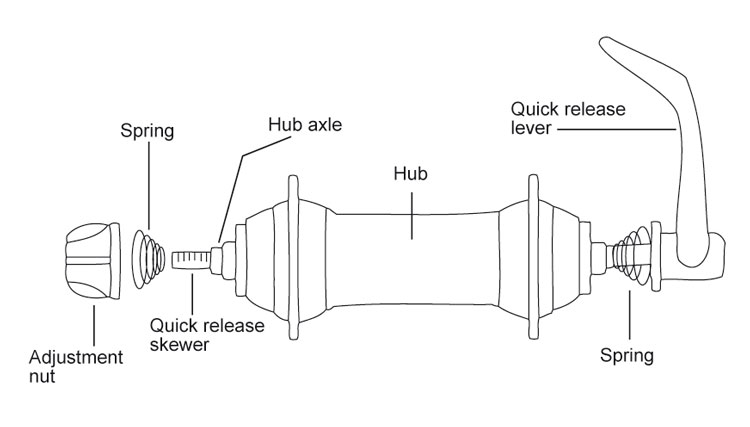
Fig. 60: Traditional quick release; diagram of parts.
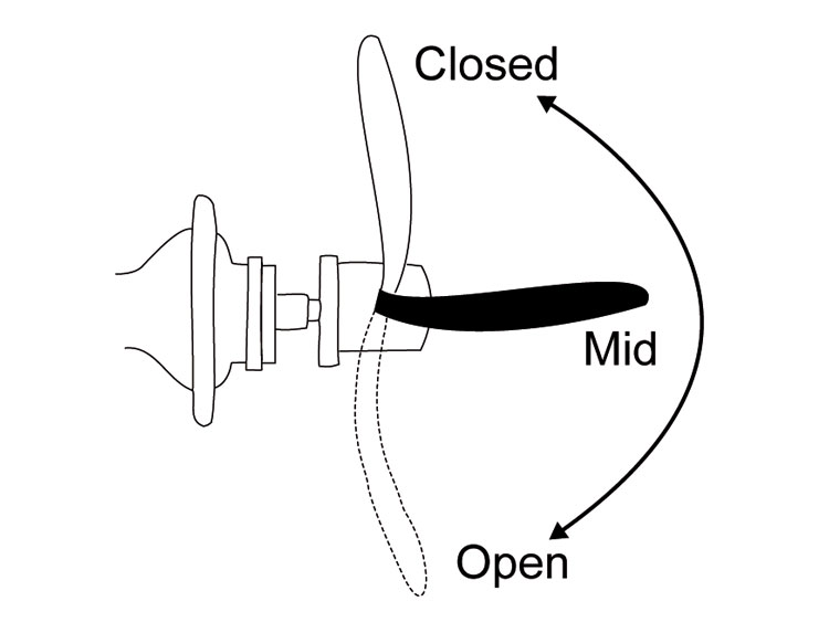
Fig 61: Positions of a quick release.
To install a wheel with a traditional quick-release:
- Move the quick release lever to the OPEN position (Fig. 61) and set the wheel so it fully engages the frame dropouts.
- With the lever in the MID position (Fig. 61), tighten the adjusting nut (Fig. 60) until it is slightly tight.
- Move the quick release into the closed position (Fig. 61) with the palm of your hand.
- A properly closed quick release lever should leave a mark on the palm of your hand from closing.
- If you can lock the lever with little or no resistance, the clamp-force is not sufficient. Go back to step 2 and tighten the adjustment nut 1/4 turn and return to step 3.
- Examine for correct quick release adjustment. With the quick release closed, lift the bicycle and hit the top of the tire with a solid blow (Fig. 30 page 29). The wheel should not come off, be loose, or move from side to side.
To remove the wheel with a traditional quick-release:
- Open the quick release lever (Fig. 61).
- Decrease the tightness of the adjustment nut; turn it approximately three full turns.
- Move wheel out of the fork or frame.
To install a wheel with a threaded axle and nut:
Some rear wheels are attached with nuts threaded on the axle. A toothed washer could be necessary between the nut and bicycle frame.
- Tighten the rear wheel axle nuts: 240-300 lb•in (27.1-33.9 N•m).
- Make sure you have correctly attached the wheel. Lift the bicycle, and hit the top of the tire with a solid blow (Fig. 30, page 29). The wheel should not come off, be loose, or move from side to side.
- If the wheel connection fails the test, do these procedures again. If you cannot correctly attach the wheel, transport your bicycle to your dealer for repair.
Cassette and Freehub Adjustments
Cassette and freehub adjustments require special tools and training and should only be performed by your local bicycle dealer.
Tighten freehub body:
354 lb•in (40 N•m).
Tighten cassette sprocket lockring:
347 lb•in (39 N•m).
Fitted Accessories (Racks and Fenders)
In addition to the parts already discussed in this chapter, your bicycle might have accessories such as fenders, lights, racks, chain guard, or kickstand. Each month, check the accessories to make sure they are correctly attached. If the part is loose or not in alignment, adjust or tighten the part, or take your bicycle to your dealer for service.
If you are attaching a rack or trailer to your bicycle, make sure your bicycle is suitable for the attachment of accessories. A rack should never be used as a seat for a person.
If you are attaching a rack or trailer to your bicycle, make sure your bicycle is suitable for the attachment of accessories. Read and follow the instructions that came with the rack or trailer. A rack should never be used as a seat for a person.
Only Install Compatible Accessories
Not all accessories are compatible or safe, so only add accessories that have the approval of the manufacturer. As an example, a child carrier puts weight high on the bicycle. This can make your bicycle less stable. Although some child carriers are compatible with some of our bicycles, always check with your dealer before making any change to your bicycle. As another example, clamping anything on a carbon part can weaken or damage the part.
WARNING |
|
| Any modification can make your frame, fork, or part unsafe. Do not sand, drill, file, remove redundant retention devices, install incompatible forks, or make other modifications. A component that is not approved or assembly that is not correct can put high stress on your bicyce or components. A frame, fork, or component with modifications could decrease your control and cause you to fall. Before you add an accessory to your bicycle or change a part of your bicycle, speak to your dealer. | |
Bearing Adjustments
Adjustments to bearing systems found on your bicycle require special training. If your bike requires adjustment to the bearings, take it to your local bicycle dealer.
Lubrication
This section shows the parts that you should lubricate, the frequency of service, and brief instructions. See your dealer for recommended grease or oil. If more instructions are necessary, see other sections of this manual or consult your dealer.
To service bearings, special tools and training are necessary, so only your dealer should do this. Some bearings are permanently sealed and do not require new grease each year.
Stem
Each year apply lubricant to the stem. To apply lubricant to a direct-connect stem, adjustment of the headset bearings is necessary. Only your dealer should do this.
To apply lubricant to a quill stem:
1. Remove the stem from the frame.
2. Clean the used grease from the stem.
3. Apply a thin layer of grease to the section of the stem-quill that will be put into the frame. Also apply grease to the stem wedge.
4. Install the stem.
Seatpost
Each year apply lubricant. Use the procedure for your frame and seatpost materials:
For a metal seatpost in a metal frame
1. Loosen the seatpost binder bolt, or release the quick-release, and remove the seatpost from the frame.
2. Clean the used grease off the seatpost.
3. Apply a thin layer of grease to the section of the seatpost that will be in the frame.
4. Put the seatpost into the frame.
5. Adjust the saddle to the correct height and align it. Tighten the seatpost binder-bolt or lock the quick-release.
Bottom Bracket
Each year, replace the grease in the bottom bracket bearings. To service bearings, special tools and training are necessary, so only your dealer should do this.
Chain
Each month, apply lubricant to the chain. Always place a rag behind the chain to prevent lubricant on other parts of the bicycle. After you apply lubricant, wipe off the excess with a rag.
Pedals
Each year, replace the grease in the pedal bearings. To service bearings, special tools and training are necessary, so only your dealer should do this.
Each year replace the grease on the pedal axles where they thread into the crank arms. There are right and left pedals, usually identified with a letter on the end of the pedal axle or on the wrench flats.
1. Remove the pedal-axles from the crankarms; turn the right pedal-axle counterclockwise, but turn the left pedal-axle clockwise.
2. Apply a thin layer of grease on the threads.
3. Install the pedals on the correct side; put the right pedal on the right crankarm and the left pedal on the left crankarm.
4. Tighten the pedal-axles.
Derailleurs
Each month, apply lubricant to all pivot points on the front and rear derailleurs, together with the derailleur pulleys on the rear derailleur.
Headset
Each year, replace the grease in the headset bearings. To service bearings, special tools and training are necessary, so only your dealer should do this.
Brakes and Brake-levers
Each three months apply lubricant to the brake-lever pivots and brake arm fixing pivots.
Wheels
Each year, replace the grease in the wheel bearings. To service bearings, special tools and training are necessary, so only your dealer should do this.
Each year, apply lubricant to wheel quick-releases. Apply two or three drops of synthetic lubricant or a light oil where the quick-release lever turns in the quick-release body.
Suspension Forks
Each month, lubricate your suspension fork. Refer to the instructions on the CD, or consult your dealer.
Each year, replace the oil in your suspension fork. To replace the oil, special tools and training are necessary, so only your dealer should do this.
Cables
Apply lubricant to a cable when you install it.
To install a cable in a cantilever brake, special tools and training are necessary, so only your dealer should do this.
To install a cable:
1. Before you remove the used cable, note its path on the frame. Loosen the cable-clamp bolt, and remove the worn cable.
2. Apply grease to the new cable where it passes through housing or guides. Install the new cable on the same path as the used cable.
3. Make sure the leaded end of the cable is installed correctly in the lever. Make sure the housing is correctly installed in the housing stop of the lever. • If necessary when you install a cable in a brake, adjust the brake again.
4. Turn the barrel-adjuster clockwise so that the threads on the barrel-
PROPER MAINTENANCE AND ADJUSTMENT CONTINUEDadjuster do not show. • For a derailleur cable, put the shift-lever in the position with the least cable tension. • For a brake cable, hold the brake closed while you do the subsequent step.
5. Tighten the cable-clamp bolt to 52-69 lb•in (6-8 Nm).
6. Cut the cable so that no more than 2” (51 mm) extends through the clamp-bolt.
7. Put a metal cap or put a bit of solder on the end of the cable to prevent a frayed cable.
8. Use the instructions for adjustment.
Bike Maintenance Schedule
Before Each Ride
- Examine the frame and fork
- Examine the wheels
- Examine tire infl ation
- Examine the brakes
- Examine the handlebar and stem
- Examine the saddle and seatpost
- Examine lights and refl ectors
- Pedals are on tight.
- Quick releases are clamping properly
Each Week
- Clean your bicycle with a damp cloth.
- Examine wheels for loose spokes.
- Apply lubricant to suspension forks.
Every Month
- Examine the attachment of the handlebar and stem.
- Examine the attachment of the saddle and seatpost.
- Examine the chain.
- Examine the cables for wear.
- Examine the operation of the shift levers and derailleurs
- Lubricate derailleurs
- Examine headset bearing adjustment
- Examine brake pads
- Examine attachment of brakepads
- Examine chain tension
- Examine wheel bearing adjustment
- Examine rims and tires for wear
- Lubricate brake levers.
- Examine crankset and bottom bracket.
- Examine the attachment of accessories.
Every Year
- Bring in bicycle for full inspection by your dealer
- Lubricate handlebar stem
- Lubricate seatpost
- Replace grease in the pedal threads and bearings.
- Replace grease in the wheel bearings
- Replace grease in the headset bearings
- Replace grease in bottom bracket
- Lubricate wheel quick releases
- Replace grease and oil in suspension forks.
Montague Corporation Limited Warranty
Claims must be made through an authorized Montague dealer. Proof of purchase is required. In addition, a warranty registration card must be completed and received by Montague Corporation before a warranty claim may be processed.
This warranty does not cover normal wear and tear, improper assembly, damage or failure due to accident, misuse, abuse or neglect, follow-up maintenance, labor charges for parts replacement or changeover, or installation of parts or accessories not originally intended or compatible with the bicycle as it was sold. Modification of the frame or components shall void this warranty.
Montague Corporation shall not be responsible for incidental or consequential damages. Some states do not allow the exclusion of incidental or consequential damages, so the above exclusion may not apply to you.
Labor charges for parts changeovers are not covered by the warranty.
This warranty gives the consumer specific legal rights, and those rights may vary from place to place. This warranty does not affect the statutory rights of the consumer.
This warranty is expressly limited to the repair or replacement of a defective item and is the sole remedy of the warranty. This warranty extends from the date of purchase, applies only to the original owner, and is not transferable.
Current Manual
Bi-Frame Owner's Manual
Download archived Owner’s Manual for Bi-Frame
Manual 2009-2015
Carrying Case Manual
Download Owner’s Manual for Carrying Case
